Vertical/short take-off and landing flying wing layout aircraft

An aircraft and layout technology, applied in the field of flying wing aircraft, can solve problems such as long take-off and landing roll distance, limited application, and requirements for enhancing pilot level

Inactive Publication Date: 2013-07-10
BEIHANG UNIV
View PDF6 Cites 22 Cited by
  • Summary
  • Abstract
  • Description
  • Claims
  • Application Information

AI Technical Summary

Problems solved by technology

[0003] However, in the field of general aviation, the flying-wing layout has not been widely used, mainly due to the inherent stability and maneuverability of the conventional flying-wing layout.
These unfavorable factors further lead to poor take-off and landing performance, long take-off and landing run distances, and high r

Method used


Image

  • Vertical/short take-off and landing flying wing layout aircraft
  • Vertical/short take-off and landing flying wing layout aircraft
  • Vertical/short take-off and landing flying wing layout aircraft

Examples


Embodiment Construction

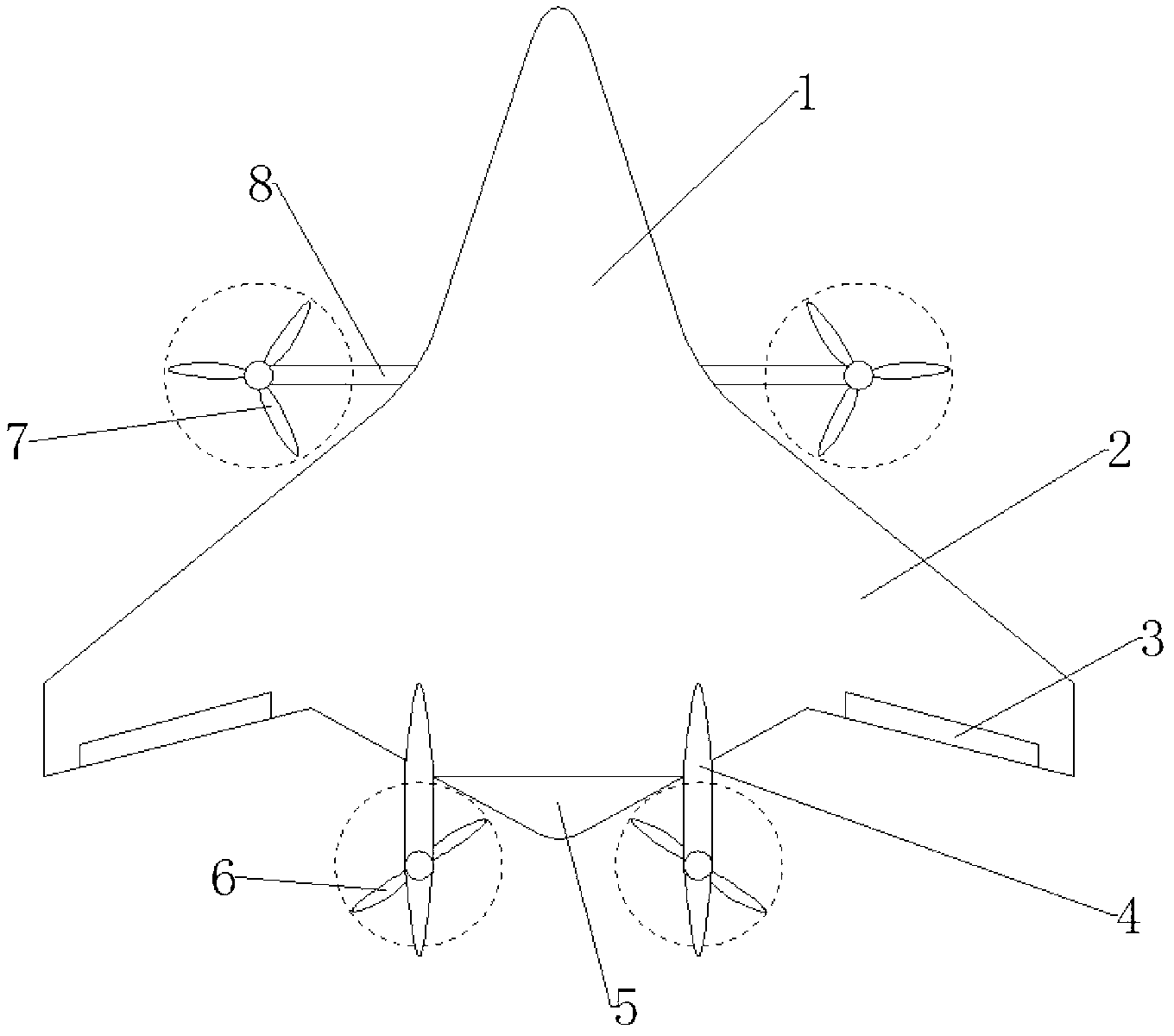
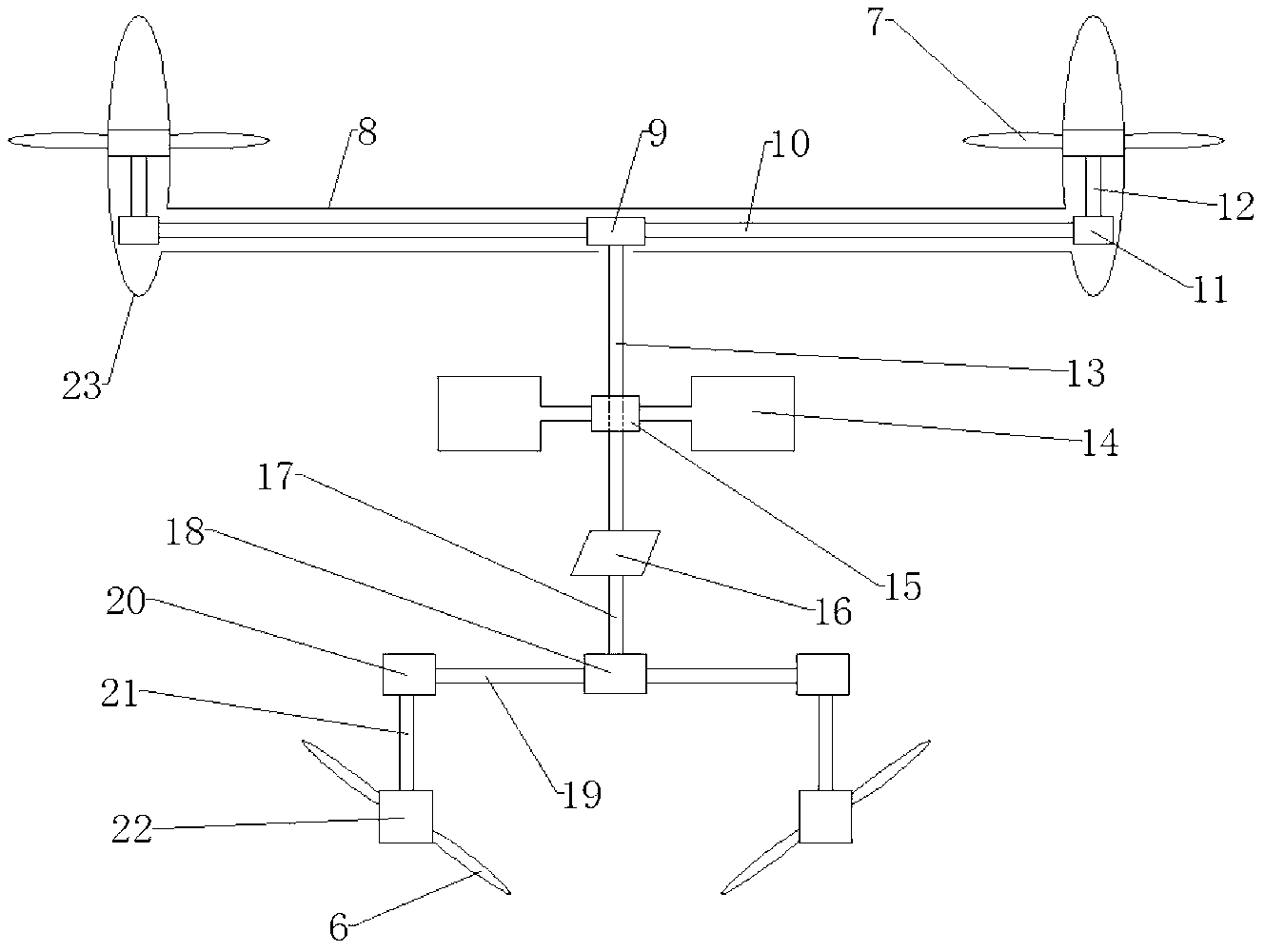
[0012] figure 1 The shown flying-wing layout aircraft according to an embodiment of the present invention includes a fuselage (1) and wings (2) integrated into one body, which has excellent aerodynamic performance. Ailerons (3) are positioned at the outer section of the wing (2) and are used for roll control during level flight. The elevator (5) is located at the rearmost part of the fuselage (1) and is used for pitch control in level flight. The twin vertical tails (4) are located behind the fuselage (1), and are used to enhance the heading stability in level flight, without any active rudder surfaces. The sleeve (8) traverses the fuselage (1), and is fixedly connected with the pods (23) of the two propellers (7) located on both sides of the fuselage (1) and in front of the wing (2). The power tilting of the front hair is realized by the rotation of the sleeve (8). When flying horizontally, the disc of the front propeller (7) is vertical, such as figure 2 The state of th...


PUM


Abstract

The invention provides a flying wing layout aircraft which comprises an aircraft body (1), aircraft wings (2), ailerons, an elevator (5) and double vertical fins (4), wherein the aircraft body (1) and the aircraft wings (2) are integrated; the ailerons (3) are positioned on the outer sections of the aircraft wings (2), and are used for rolling control in level flight; the elevator (5) is positioned at the rearmost part of the aircraft body (1), and is used for pitching control in level flight; and the dual vertical fins (4) are positioned at the rear part of the aircraft body (1), and are used for enhancing the flight direction safety in level flight. The flying wing layout aircraft provided by the invention has the advantages that the aircraft body integration technique inherits the excellent pneumatic property of the flying wings, and larger internal space is provided; the weight distribution is more reasonable, and the structure is lighter, so that the load and the voyage are increased; front air screws which are arranged in an engine and tilt and rear air screws which are fixed and can be accommodated in the vertical fins achieve the capability of vertical/short take-off and landing, and the interference to the whole pneumatic appearance of the aircraft is lowered greatly; and the connection shaft design among engines greatly improves the reliability of a dynamic system, avoids the dangerous situation of invalidity after taking off, and guarantees the flight safety in vertical/short take-off and landing.

Description

technical field [0001] The invention relates to a short-distance / vertical take-off and landing flying-wing aircraft, belonging to the technical field of fixed-wing aircraft design in aviation aircraft. Background technique [0002] Due to excellent aerodynamic and structural weight characteristics, good stealth performance and large internal space, in the military field, the flying wing layout has been used maturely, such as the US B-2 Ghost stealth bomber, and many countries are currently researching and developing All unmanned combat or reconnaissance aircraft have adopted the flying wing layout, making the flying wing layout a research hotspot in the field of military aircraft. [0003] However, in the field of general aviation, the flying-wing layout has not been widely used, mainly due to the inherent disadvantages of stability and maneuverability of the conventional flying-wing layout. These unfavorable factors further lead to poor take-off and landing performance, lo...

Claims


Application Information

Patent Timeline
IPC IPC(8): B64C39/06B64C27/26B64D35/04
Inventor 王维军刘江涛
Owner BEIHANG UNIV
Why Eureka
Try Eureka