Lighting control switch

A lighting control and switch technology, applied in electronic switches, lighting devices, computer control, etc., can solve problems such as eye glare and poor sleep, and achieve the effects of reducing power consumption, improving convenience, and improving ease of use

Inactive Publication Date: 2007-11-28
MATSUSHITA ELECTRIC WORKS LTD
View PDF1 Cites 13 Cited by
  • Summary
  • Abstract
  • Description
  • Claims
  • Application Information

AI Technical Summary

Problems solved by technology

Therefore, when getting up in the middle of the night to go to the bathroom, if the lighting control switch is used to turn on the lighting loads in the corridor lights, stair lights, or the bathroom, these lighting loads will all be on, which may cause eye glare or wakefulness. poor sleep problems

Method used


Image

  • Lighting control switch
  • Lighting control switch
  • Lighting control switch

Examples


no. 1 approach

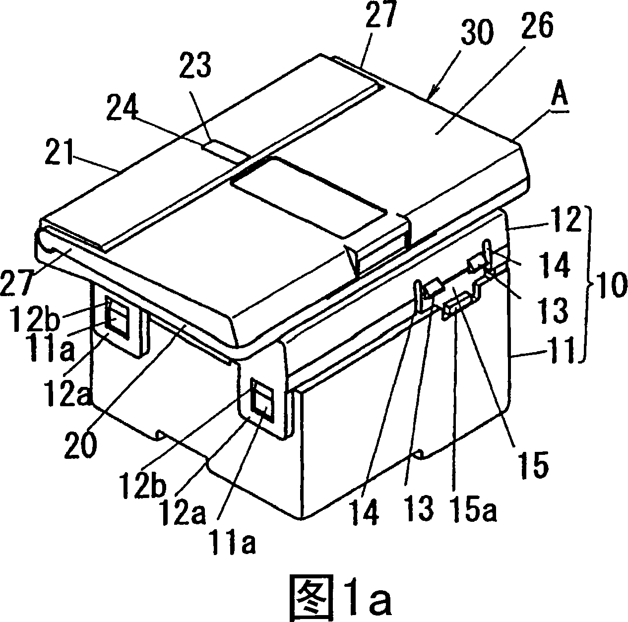
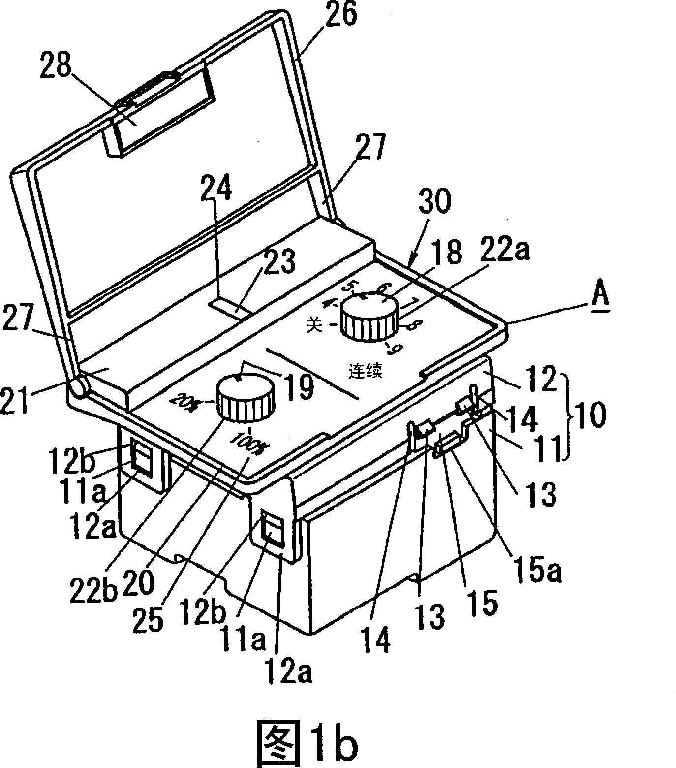
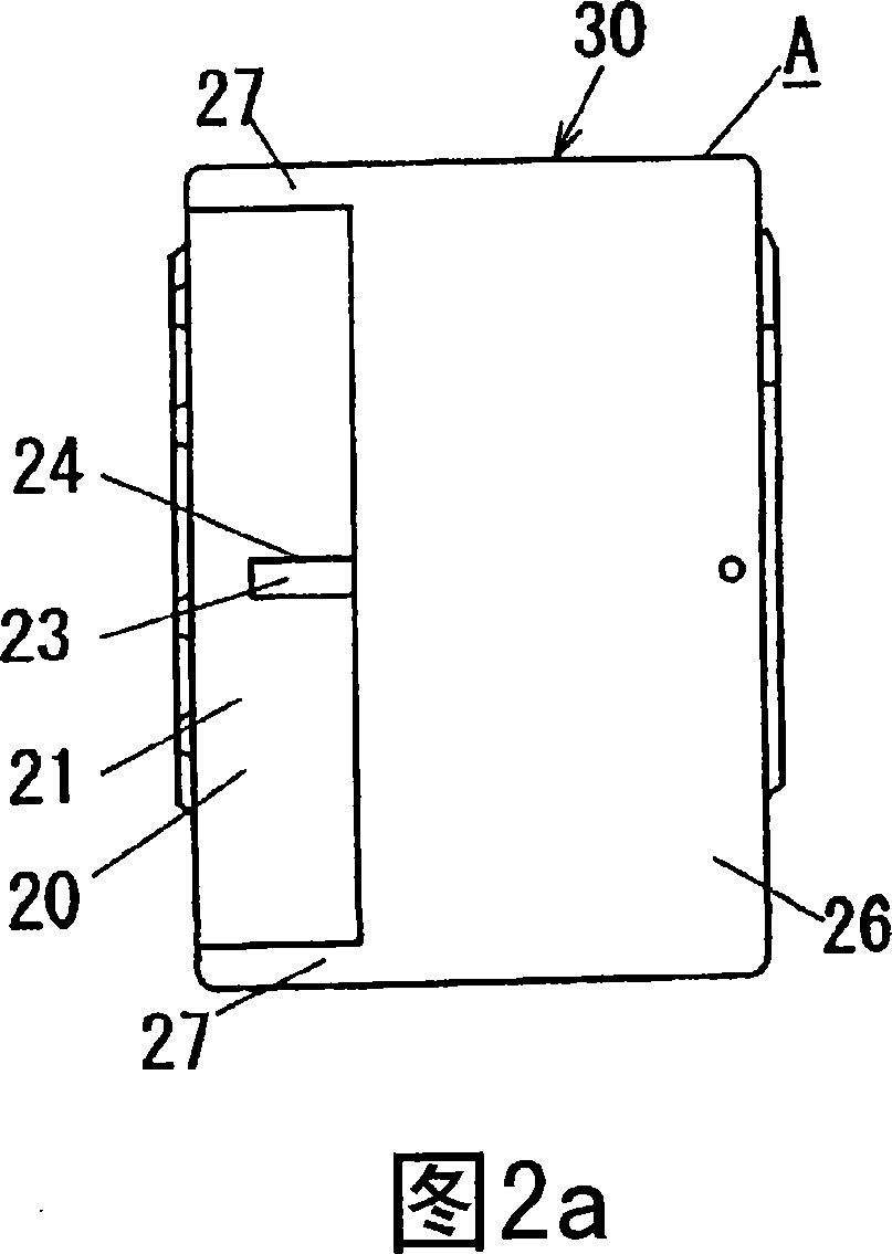
[0040]A first embodiment of the present invention will be described with reference to FIGS. 1 to 8 . The lighting control switch A of the present invention is used in order to turn on and off the power supply to lighting loads such as corridor lights or stair lights installed in corridors or stairs, and has the following functions: during a preset time period in a day (such as In the middle of the night, etc.), the lighting load is dimmed and turned on according to the ON operation, and in other time periods, the lighting load is fully brightened according to the ON operation.

[0041] Fig. 4 shows the control circuit of the lighting load La, the lighting load La uses the lighting control switch A (main switch) and the sub-switch B (external switch) of this embodiment, for example, the lighting control switch A is set at one end of the corridor, the The sub-switch B is set at the other end of the corridor, which can make the lighting load La set in the corridor turn on or off ...

no. 2 approach

[0085] A second embodiment of the present invention will be described with reference to FIGS. 9 to 11 . In this embodiment, the lighting control switch A described in the first embodiment is provided with a function for controlling on / off of the ventilating fan F, for example, for controlling the lighting load La and the ventilating fan F installed in the bathroom in conjunction. In addition, since the configuration other than the configuration related to the control of the ventilation fan F is the same as that of the first embodiment, the same reference numerals are assigned to the same components, and description thereof will be omitted.

[0086] FIG. 9 is a circuit diagram of a control circuit of a lighting load La and a ventilation fan F using the lighting control switch A of this embodiment. In addition to the configuration described in Embodiment 1, the lighting control switch A has a connection terminal Td between the connection terminal T and a series circuit connectin...


PUM


Abstract

The present invention relates to a lighting control switch, which weakens the lamp output of the lighting load at the late night period and the like prescribed time periods, and illuminates the surrounding more clearly at other time periods. At the front part of the switch body (10) of the lighting control switch (A), it is arranged with a press switch which does opening/closing to the lighting load, a rotating handle (18) of the light modulation time period setting switch which sets the light modulation time period, and a operating handle (20) which is rotating-freely arranged and impels thepress switch at back side according to the rotating operation. The operating handle (20) is arranged with open window (22a) which is used to expose the rotating handle (18), and is installed with an operating handle cover (26) which is opened and closed freely at the closed position where it covers the rotating handle 18 and the open position where it exposes the rotating handle 18. The lighting control switch (A) switches on and cuts off the electricity supply to the lighting load according to the operation of the press switch, when the press switch does open operation at the light modulation time period, it makes the lighting load illuminate with less brightness.

Description

technical field [0001] The present invention relates to a lighting control switch for controlling the power supply to a lighting load. Background technique [0002] This kind of lighting control switch is mostly located in corridors, stairs, etc., and is used to switch on and off the power supply to lighting loads such as corridor lights and stair lights. [0003] In addition, conventionally there is a lighting control switch (for example, refer to Patent Document 1), which performs timing control of other loads such as ventilation fans in addition to turning on and off the power supply of lighting loads installed in the bathroom. . [0004] Patent Document 1: Japanese Patent Application Laid-Open No. 2000-100293 (paragraphs 0031 to 0046, and FIGS. 2 to 4 ). [0005] In the lighting control switch described above, only the power supply to the lighting load is turned on and off, so the lighting output of the lighting load is always kept constant regardless of the time perio...

Claims


Application Information

Patent Timeline
Patent Type & Authority Applications(China)
IPC IPC(8): H05B37/02G05B19/04G05B15/02H03K17/72H02M5/257
CPCY02B20/42Y02B20/40F21V23/04F24F11/0001
Inventor 向井达哉时实敏昭
Owner MATSUSHITA ELECTRIC WORKS LTD
Why Eureka
Try Eureka