
Tilt-rotor fixed wing aircraft with vertical take-off and landing function

A tilt-rotor, vertical take-off and landing technology, applied in vertical take-off and landing aircraft, rotorcraft, aircraft control and other directions, can solve problems such as the wasted weight of aircraft structure, too many auxiliary supporting facilities, and shortened aircraft cruising radius, etc. Achieve the effect of performing tasks quickly, taking off and landing anytime, anywhere, and saving the weight of the structure

Active Publication Date: 2016-11-23
北京奇正数元科技股份有限公司
View PDF5 Cites 24 Cited by
  • Summary
  • Abstract
  • Description
  • Claims
  • Application Information

AI Technical Summary

Benefits of technology

This patented design allows for efficient takeoff and landings on drones without requiring expensive equipment or heavy structures at their destination. It also saves space while still providing stability during high altitude flights. Additionally, it uses advanced technologies like carbon fibers frames (CF) made from polyimide resin impregnated into molded plastic sheets instead of traditional materials such as aluminum alloys due to its lightweight properties compared to other options. Overall, these technical improvements make dronies highly versatile and cost-effective.

Problems solved by technology

The technical problem addressed in this patented text relates to how complex an airborne vehicle's structures are designed for carrying passengers during flight operations due to environmental factors such as altitude changes or wind conditions that affect its ability to lift heavy loads effectively without reducing their lifespan.

Method used


Image

  • Tilt-rotor fixed wing aircraft with vertical take-off and landing function
  • Tilt-rotor fixed wing aircraft with vertical take-off and landing function
  • Tilt-rotor fixed wing aircraft with vertical take-off and landing function

Examples


specific Embodiment

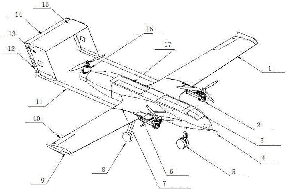
[0034] As a specific embodiment, the front end of the fuselage is provided with a pitot tube 4;

[0035] As a specific embodiment, a direction light 9 is provided at the end of the wing.

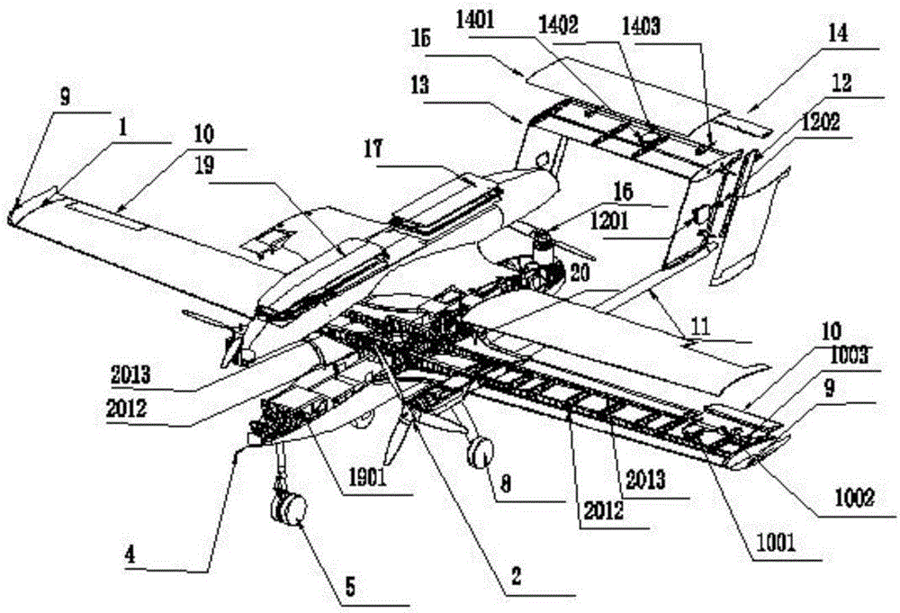
[0036] As a specific embodiment, the wing is provided with a quick-release structure. The quick-release mechanism uses the fuselage front beam 2012 and the fuselage rear beam 2013 to fix through concave and convex positions, and then uses the taper pin 20 to perform pre-tightening connection.

[0037] As a specific embodiment, the fuselage is provided with an external cooling fin 6 at the place where the motor of the pitching and tilting power device is installed.

[0038] See Figure 4 , as a specific embodiment, the anti-torsion balance power device 16 includes a propeller 1601, a power motor 1602, a motor mounting base 1603, a rotating assembly 1604, a rear end surface 1605 of the fuselage, an electric regulator 1606, a drive transmission mechanism 1607, a reinforced end surface 1608, S...


PUM


Abstract

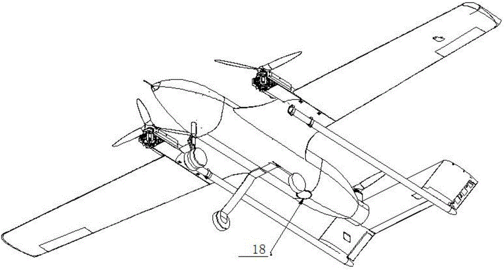
The invention relates to a tilt-rotor fixed wing aircraft with a vertical take-off and landing function. The tilt-rotor fixed wing aircraft comprises an aircraft body, wings and a tail, wherein the wings and the tail are mounted on the aircraft body. Pitching and tilting power devices are arranged on the left side and the right side of the aircraft body. A front landing gear and a main landing gear are arranged at the bottom of the aircraft body. An equipment hatch is arranged on the upper portion of the aircraft body, and an aviation telemetering camera is arranged in an equipment cabin. A control cabin hatch is arranged on the upper portion of the aircraft body, and a control device is arranged in a control cabin. A reverse-torsional balance power device is arranged on the rear portion of the aircraft body. The wings are mounted on the two sides of the aircraft body and provided with wing control planes. The tail is connected with the aircraft body through tail supporting rods and comprises a horizontal tail, a pitching control plane, a vertical tail and a yaw control plane. The tilt-rotor fixed wing aircraft has the advantages that the vertical take-off and landing, tilting and level flight of the aircraft can be achieved through one power system, take-off and landing of an unmanned aerial vehicle are not limited by fields, the structural weight can be better reduced, the aircraft can fly more stably, the flying time is longer, operation is simpler, and the flying process is more intelligent.

Description


Claims


Application Information

Patent Timeline
Owner 北京奇正数元科技股份有限公司
Learn More