Land and air double-used aircraft

A dual-use technology for land and air, aircraft, applied to aircraft, vertical take-off and landing aircraft, vehicles that can be converted into aircraft, etc., can solve the problems of large vibration and noise, large volume and weight of aircraft, and achieve the effect of overcoming dead weight

Inactive Publication Date: 2010-11-17
杨朝习
View PDF5 Cites 24 Cited by
  • Summary
  • Abstract
  • Description
  • Claims
  • Application Information

AI Technical Summary

Problems solved by technology

[0006] The purpose of the present invention is to provide a dual-purpose aircraft for land and air, to solve the problems of large volume, heavy weight, vibrat

Method used


Image

  • Land and air double-used aircraft
  • Land and air double-used aircraft
  • Land and air double-used aircraft

Examples


Embodiment 1

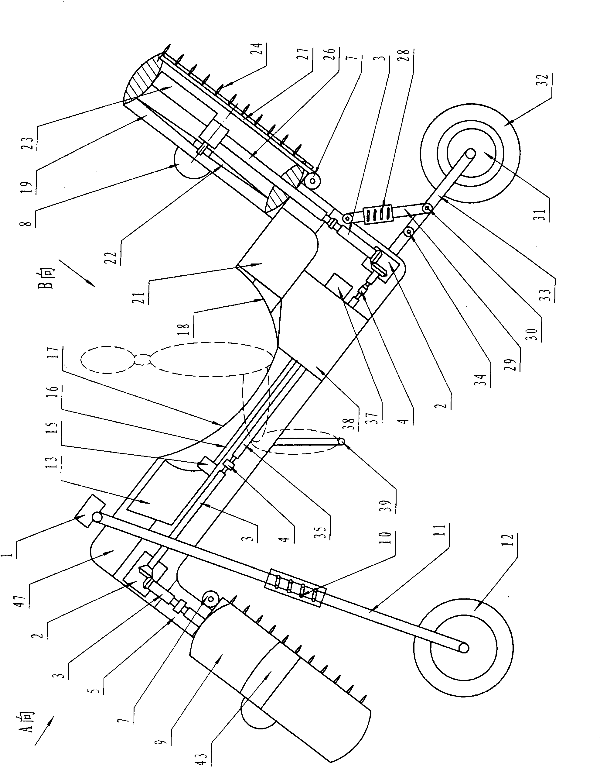
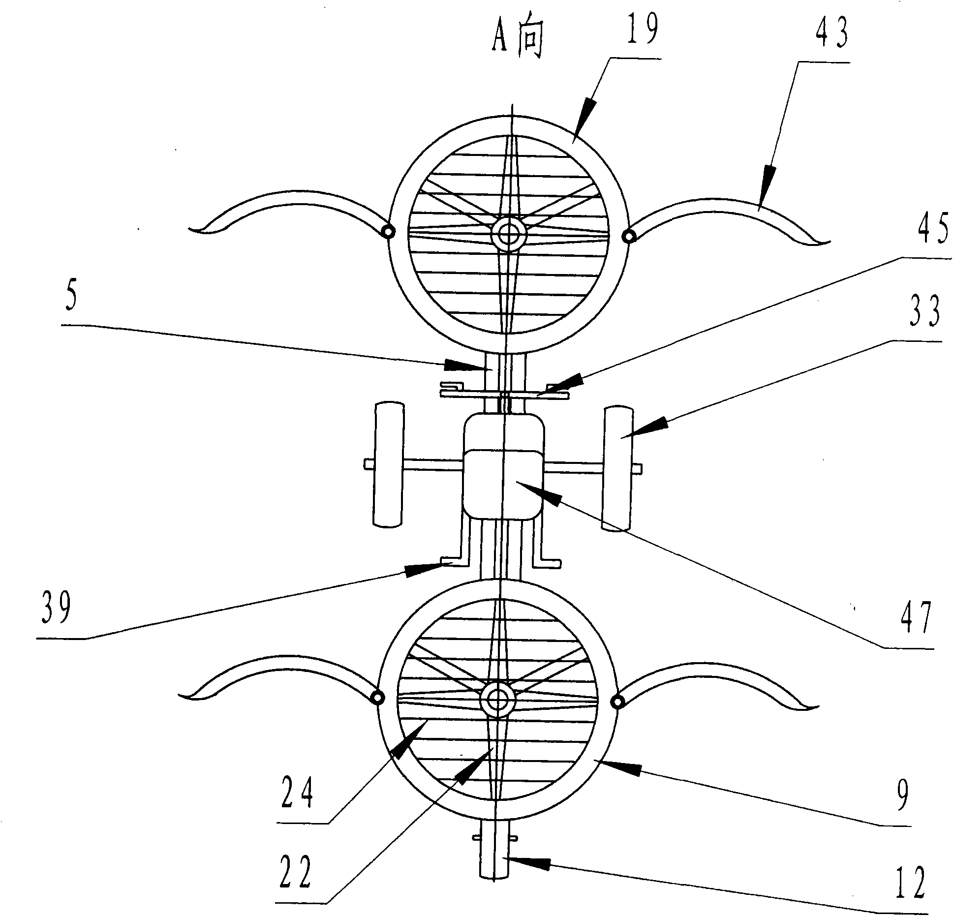
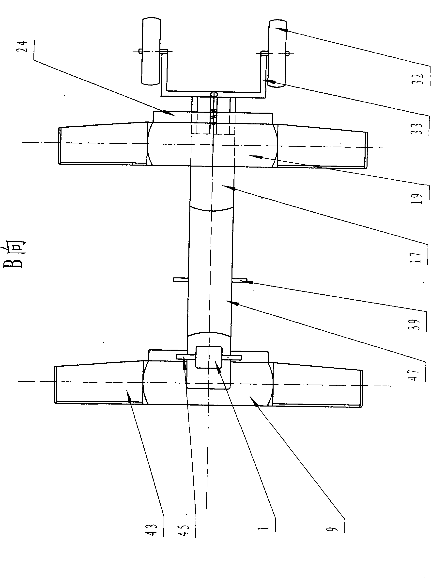
[0031] Such as Figure 1-Figure 3 As shown, a kind of basic structural form of this ground-air dual-purpose aircraft is that the front and rear ends of the body 47 are respectively connected with the pipeline girder 5 that is perpendicular to the body and protrudes downwards and upwards respectively, and the pipeline girder 5 at the front end of the body 47 The lower end of the 5 is connected with a front ducted fan 9; the upper end of the pipeline girder 5 at the rear end of the body 47 is connected with a rear ducted fan 19. The axis lines of the propellers in the front and rear ducted fans are kept parallel to the axis lines of the body 47 respectively. Certainly, the included angle of pipeline girder 5 and body 47 also can change slightly, or the axis line of front and rear duct fan and the axis line of body 47 keep a very small angle, but front and rear duct The fans are preferably kept in a column opposite to the front and rear ( image 3 ). In short, the windward sid...

Embodiment 2

[0048] Such as Figure 5 As shown, the basic structure of the present embodiment is the same as that of Embodiment 1, except that the rear ducted fan 19 is changed into two side by side, and only the front ducted fan 9 is provided with a folding wing 43, and the rear ducted fan 19 Not only the wings are established, but the tops of the two rear ducted fans 19 are connected with reinforcing plates 40, and the ducts of the reinforcing plates and the rear ducted fans are used as quasi-wings. Two rear ducted fans 19 arranged side by side are supported and connected by two pipe girders 5 and transmit power. The two pipeline girders 5 are arranged in a V shape, and both are vertically connected with the body 47 .

Embodiment 3

[0050] Such as Figure 6 As shown, the basic structure of this embodiment is the same as that of Embodiment 1, and the rear ducted fans 19 are also two side by side. Foldable wings 43 are arranged on both sides of the duct of the front ducted fan 9, and no reinforcing plate is established between the two rear ducted fans 19, but are respectively arranged on the outer end sides of the two rear ducted fans. A wing 43. The two rear ducted fans 19 are respectively arranged at both ends of the transverse transmission shaft tube 50 , and the transverse transmission shaft tube 50 is connected to the upper end of the pipeline girder 5 through a tilting mechanism 51 . In this way, the two rear ducted fans 19 can be tilted at a certain angle by the rotation of the transverse transmission shaft tube 50, forming a power (ducted fan) tilting structure.

[0051] In this embodiment, a fixed connection mechanism is also provided at the position of the tilting mechanism 51 so that the two re...


PUM


Abstract

The invention relates to a land and air double-used aircraft, comprising an aircraft body, an aircraft controller, an engine and an undercarriage, wherein a front ducted fan which faces the wind at upper front is connected with the lower part of the front end of the aircraft body; a rear ducted fan which faces the wind at upper front is connected with the upper part of the rear end of the aircraft body; the front ducted fan and the rear ducted fan form a Z-shaped structure with the aircraft body; the front ducted fan and the rear ducted fan are respectively connected with a guide plate and a stream guiding grating; a pull rod pulling the stream guiding grating is connected with a pull rod electric motor; the undercarriage comprises a front support and a rear support which are respectively arranged at the frond end and at the rear end of the aircraft body; a front wheel is connected with the lower end of the front support; a rear wheel is connected with the lower end of the rear support; and the front wheel and the rear wheel are driven by a wheel-and-axle electric motor or a motorcycle engine. The invention discloses a land and air double-used light aircraft which can take off and land vertically, flies horizontally and can run on the ground normally, effectively solves the problem that the existing aircraft has complicated structure, heavy weight and low safety performance, and is beneficial for the aircraft to be used early and safely.

Description

technical field [0001] The invention relates to a small aircraft, in particular to an aircraft with both ground and air functions. Background technique [0002] No. CN200910038258.X patent application discloses a double-ducted propeller vertical take-off and landing flying car. The car's four wheels double as the aircraft's landing gear. When taking off and landing, the flying car relies on the upward thrust provided by two ducted fans arranged on the car body to achieve vertical take-off and landing. When flying in the air, the front part of the flying car should be sunk and tilted at a certain angle (similar to that of a helicopter), so that the two ducted fans can provide a certain horizontal component force to push the aircraft to achieve horizontal flight. Its main disadvantages are: [0003] 1. Since the two ducted fans are all arranged on the car body, the total length of the car body must be lengthened, and an overly long car body will increase the weight of the c...

Claims


Application Information

Patent Timeline
IPC IPC(8): B60F5/02
CPCB64C29/0025
Inventor 杨朝习
Owner 杨朝习
Why Eureka
Try Eureka