Wing rib-free rapid water injection and drainage wing suitable for sea and air across amphibious unmanned aerial vehicle

An unmanned aerial vehicle and cross-sea technology, applied in the field of wings, can solve the problems of restricting unmanned aerial vehicles, unfavorable water flow, and difficulty in the average density of unmanned aerial vehicles. The effect of machine weight

Active Publication Date: 2013-06-26
北京华信智航科技有限公司
View PDF3 Cites 10 Cited by
  • Summary
  • Abstract
  • Description
  • Claims
  • Application Information

AI Technical Summary

Problems solved by technology

[0006] At present, the inner skeleton of the wing of the UAV generally includes a longitudinal skeleton (spar, longitudinal wall, and stringer) and a transverse skeleton (wing ribs). The transverse skeleton ribs have the same shape as the wing section and are distributed along the wing span There are several ribs. Due to the existence of the rib structure, the space inside the wing along the span direction is blocked by the ribs. The wing with this structure is not conducive to the flow of water inside the wing (water injection and drainage), and it is not easy to By changing the overall density of the wing to adjust the average density of the UAV itself, it limits the operation of the UAV in the water environment

Method used


Image

  • Wing rib-free rapid water injection and drainage wing suitable for sea and air across amphibious unmanned aerial vehicle
  • Wing rib-free rapid water injection and drainage wing suitable for sea and air across amphibious unmanned aerial vehicle
  • Wing rib-free rapid water injection and drainage wing suitable for sea and air across amphibious unmanned aerial vehicle

Examples


Embodiment Construction

[0046] The present invention will be further described in detail below in conjunction with the accompanying drawings.

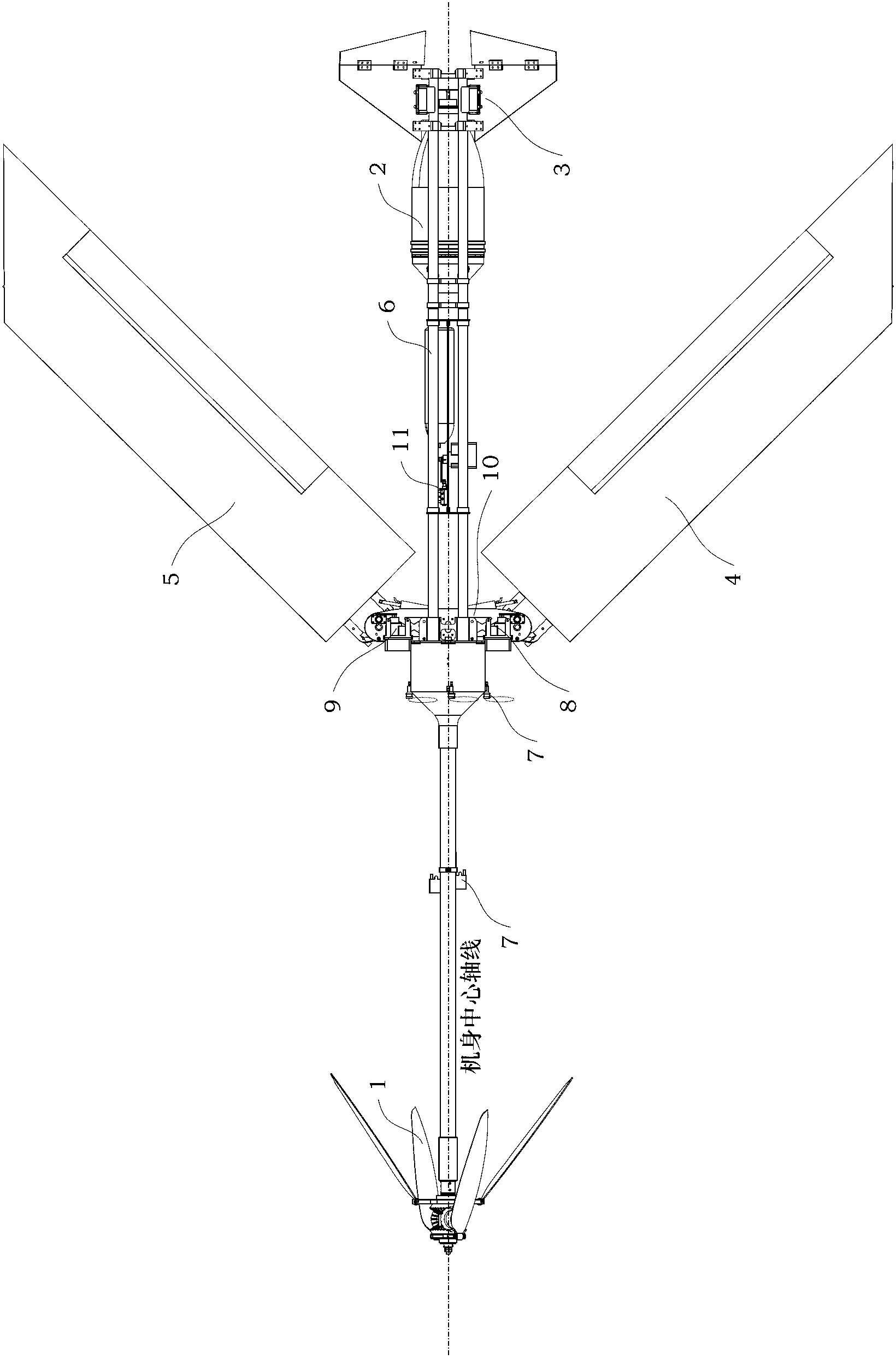
[0047] A top view structure suitable for amphibious UAVs across sea and air such as figure 1 , Image 6 As shown, the UAV includes an air propulsion device 1, an underwater propulsion assembly 2, a V-shaped tail assembly 3, a left wing assembly 4, a right wing assembly 5, a girder fuselage 6, a water air bag erection assembly 7, and a left wing drive Assembly 8, right wing drive assembly 9, folding wing support body 10 and folding and unfolding conversion assembly 11;

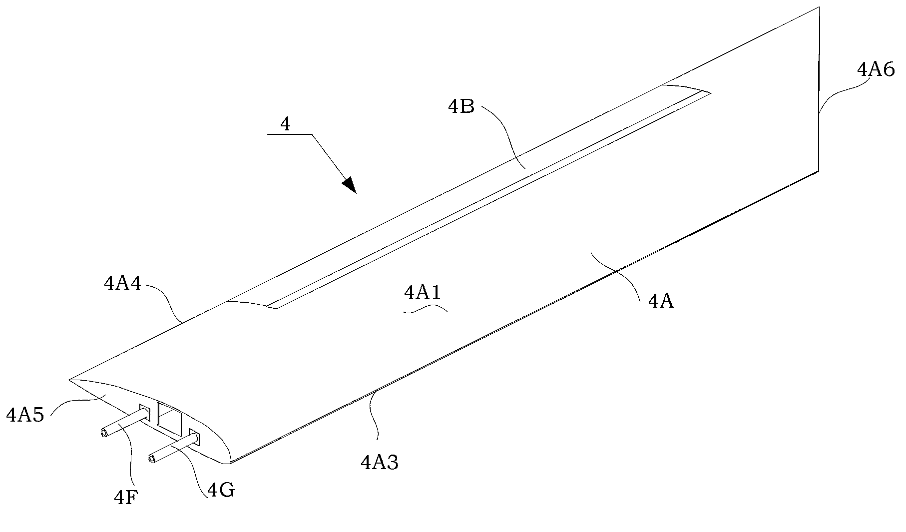
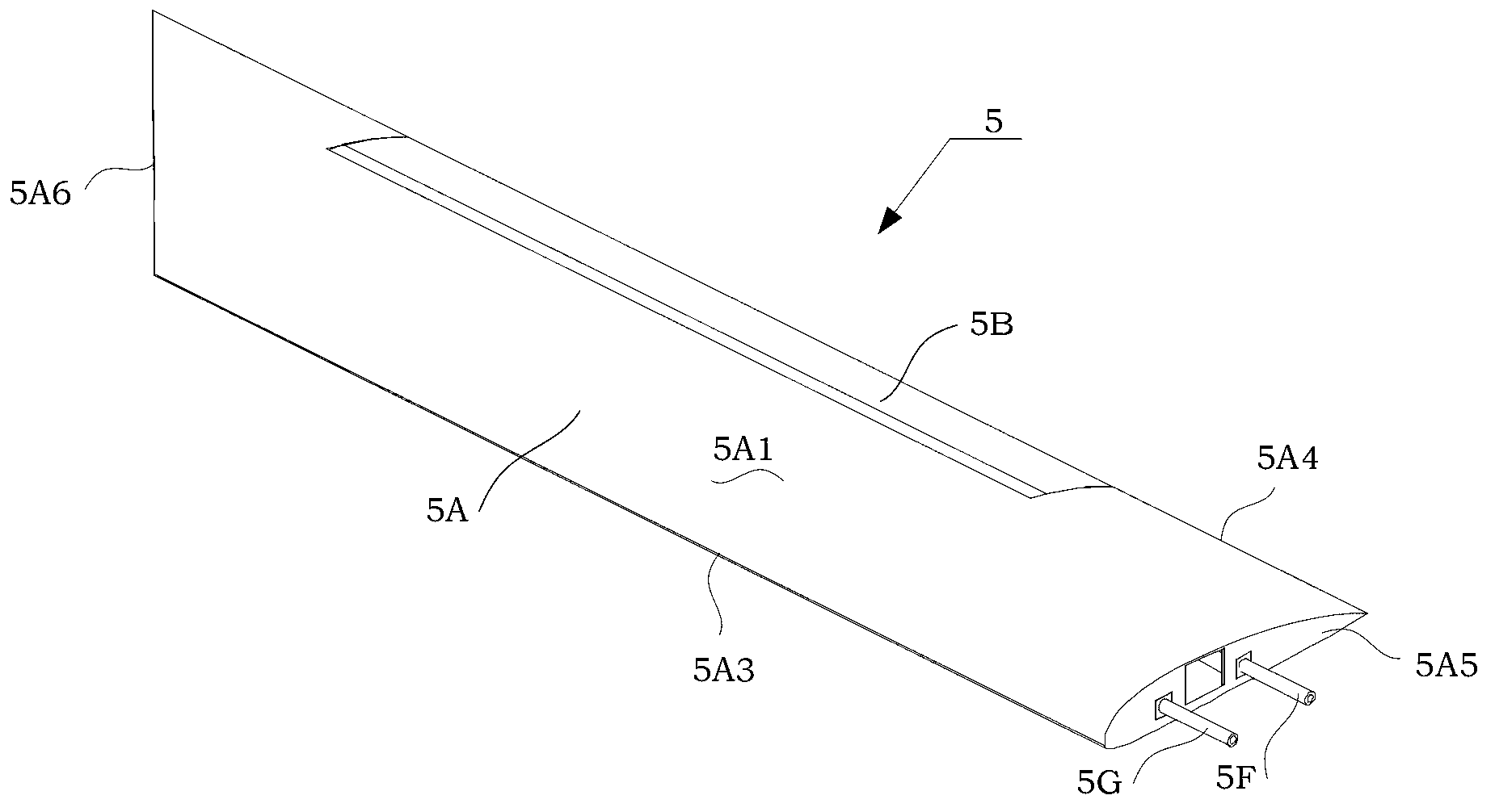
[0048] Wherein, the left wing assembly 4, the left wing drive assembly 8, the right wing assembly 5, the right wing drive assembly 9 and the folding wing support body 10 constitute the wing part of the drone;

[0049] Wherein, the left wing assembly 4 has the same structure as the right wing assembly 5, and is installed symmetrically with the central axis of the fuselage;

[0050] Wherein,...


PUM


Abstract

The invention discloses a wing rib-free rapid water injection and drainage wing suitable for a sea and air across amphibious unmanned aerial vehicle. The wing comprises a left wing component and a right wing component, wherein the left wing component and the right wing component have the identical structure and are symmetrically arranged around the central axis of the body; the wing component comprises a primary wing, a secondary wing, a wing steering engine, a wing rudder, a wing connecting shaft, a carbon fiber rod and a wing longitudinal rib fixing rod; the secondary wing is arranged on the rear edge concave part of the primary wing through the wing connecting shaft; the wing rudder is arranged on the secondary wing; the wing steering engine is arranged on the primary wing; and the carbon fiber rod and the wing longitudinal rib fixing rod are arranged in a wing cavity of the primary wing. A cavity wing rib-free structure is formed in the main wing, so that when the unmanned aerial vehicle enters water, the inner wing cavity can be rapidly filled with water, the average density of the whole body is rapidly increased due to the water injected into the wing part, and underwater navigation is promoted; and meanwhile, when the unmanned aerial vehicle vertically takes off from the water surface, water in the wing cavity can be rapidly discharged, so that the density of the whole body is rapidly reduced, and air flight is promoted.

Description

technical field [0001] The invention relates to a wing for an unmanned aerial vehicle, more particularly, to a ribless rapid water injection and drainage wing suitable for amphibious unmanned aerial vehicles across the sea and air. Background technique [0002] UAV is the abbreviation of unmanned aerial vehicle, and the English abbreviation is UAV (Unmanned Aerial Vehicle). [0003] The most important requirement for the design of the UAV is to be as light as possible while the fuselage system is strong enough. However, UAVs under various mission load requirements leave very limited space and quality quotas for motion transmission mechanisms. It is necessary to flexibly and efficiently convert basic engineering driving motions, such as high-speed rotation, into favorable controlled motions. The basic aviation transmission methods include direct drive, proportional amplification drive, electric servo drive and hydraulic servo drive. [0004] UAV is an unmanned aircraft oper...

Claims


Application Information

Patent Timeline
Patent Type & Authority Applications(China)
IPC IPC(8): B64C3/00B64C37/00
Inventor 梁建宏杨兴帮吴海亮曾庆儒王田苗
Owner 北京华信智航科技有限公司
Why Eureka
Try Eureka