Vertical/short take-off and landing aircraft

a technology of vertical/short take-off and landing, which is applied in the direction of vertical landing/take-off aircraft, process and machine control, instruments, etc., can solve the problems of yaw of aircraft and net change, and achieve the effect of improving aircraft safety, simple construction and maintenance, and improving efficiency in horizontal flight mod

Inactive Publication Date: 2012-09-04
LAPCAD ENG
View PDF13 Cites 23 Cited by
  • Summary
  • Abstract
  • Description
  • Claims
  • Application Information

AI Technical Summary

Benefits of technology

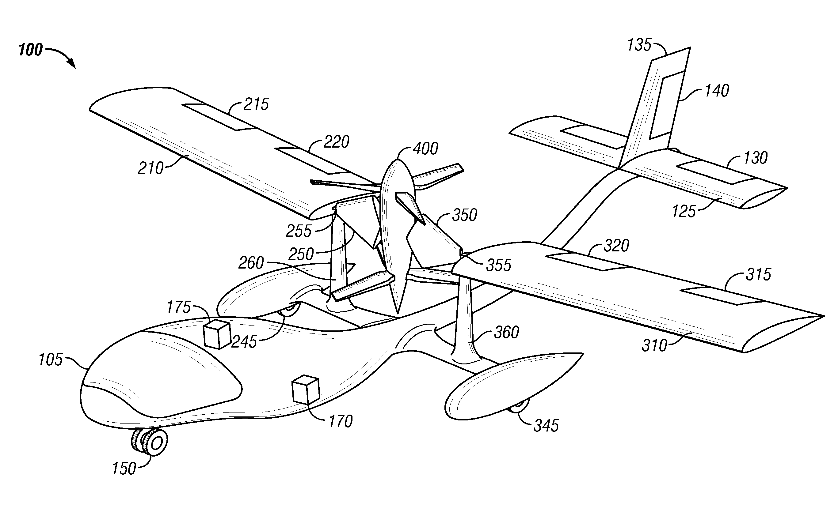
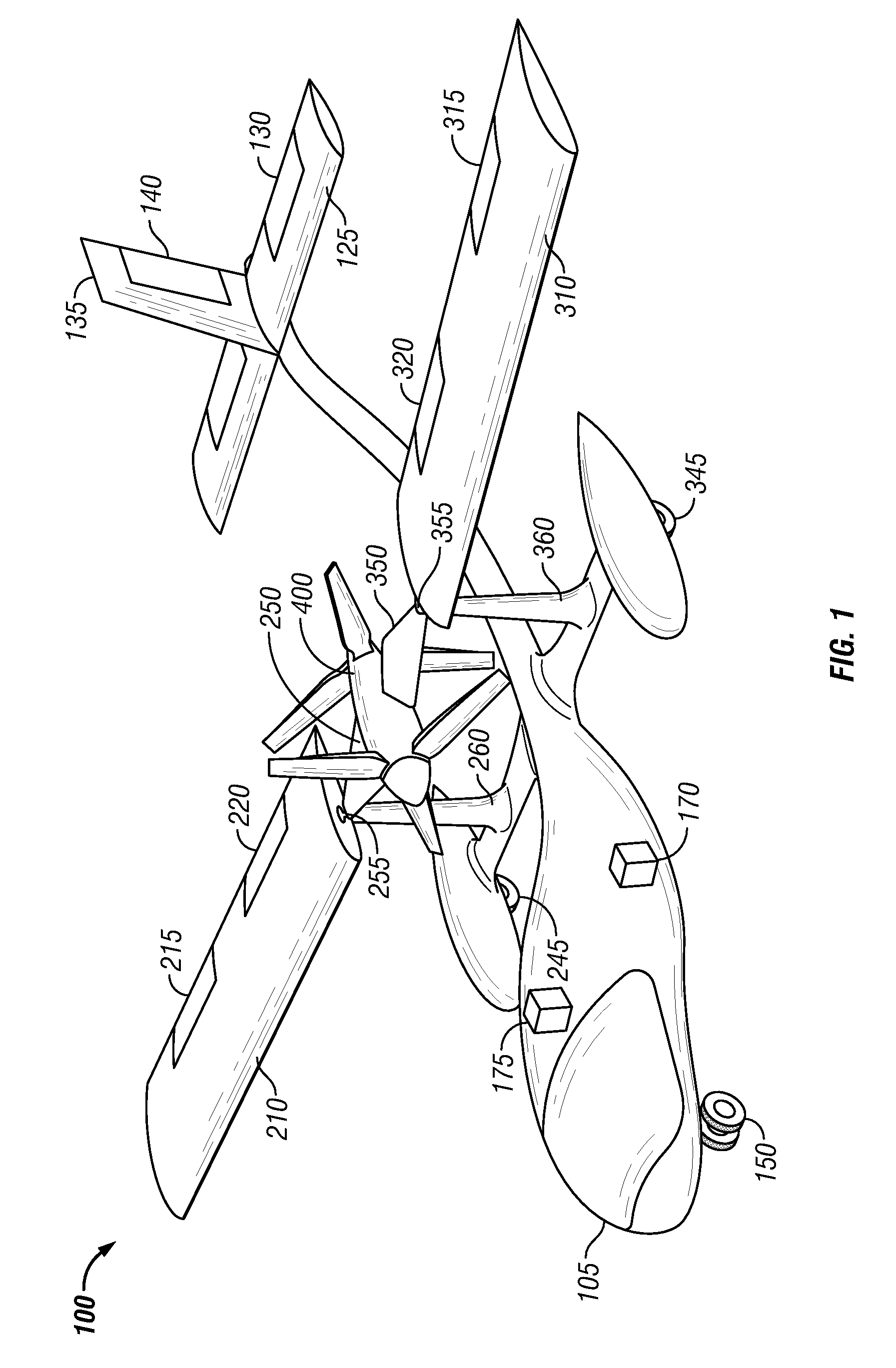
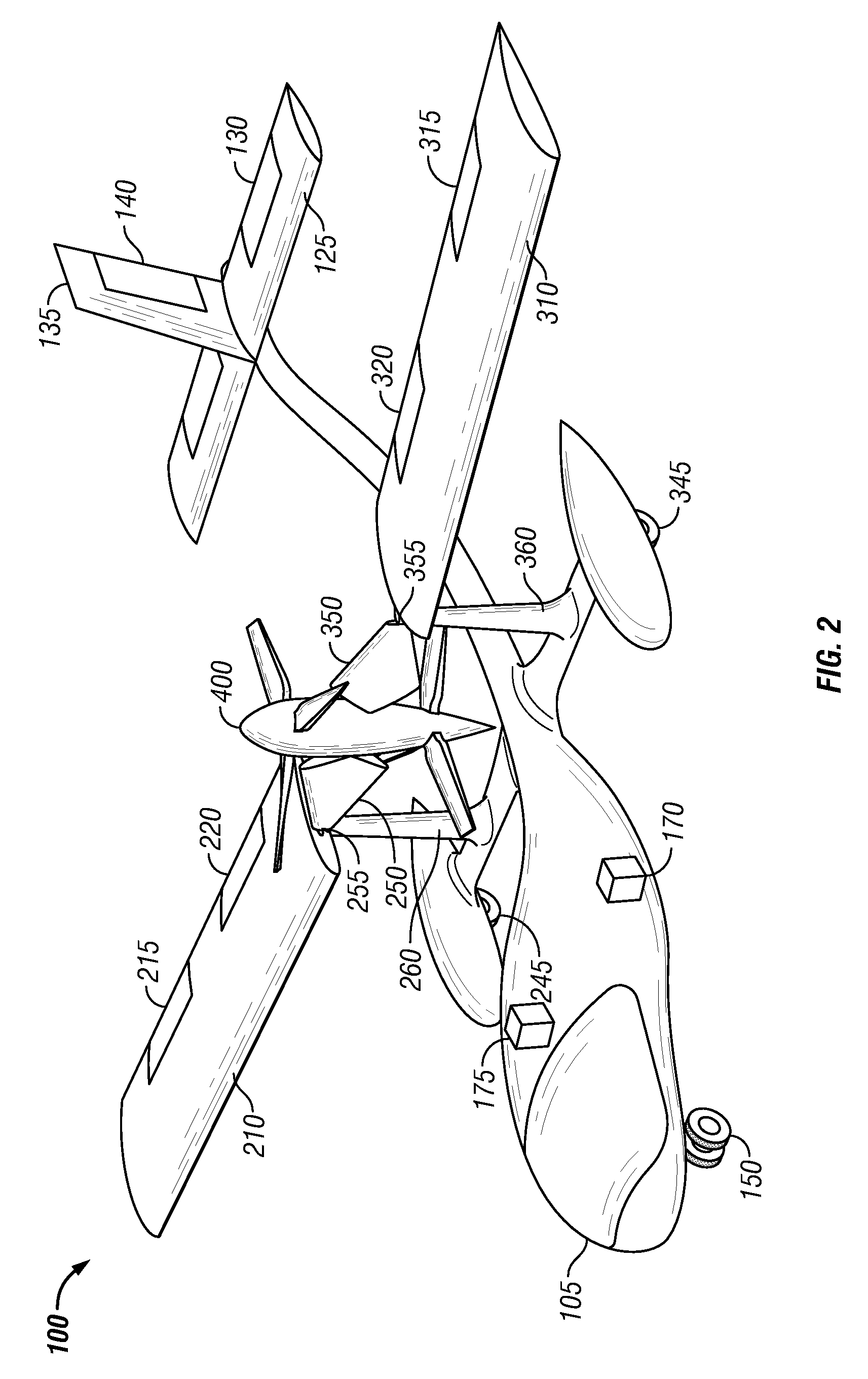
[0012]In a preferred embodiment, a pair of inline counter-rotating propellers are employed on a V / STOL aircraft that does not require a transmission to create the counter rotation of the individual propellers. Additionally, a preferred embodiment provides a simple mechanism for stopping the rotation of one propellers of an inline counter-rotating propeller assembly for improved efficiency in horizontal flight mode. A V / STOL aircraft embodying the invention is simple to build and maintain and is adaptable to either piloted or unpiloted applications, providing benefits to aircraft of all scales and sizes. Furthermore, two engines improve aircraft safety during both horizontal flight mode and vertical hover mode. In horizontal flight mode, loss of power from one engine will not require re-trimming of the aircraft because the engines are mounted inline. In vertical hover mode, loss of one engine will still allow the remaining engine to maintain a survivable rate of descent. The improvements described herein are applicable to tilt-wing aircraft and tilt-rotor / tilt-propeller aircraft with simplified flight controls for vertical hover mode. Herein after, references to tilt-rotor / tilt-propeller aircraft apply equally to tilt-wing aircraft (the term V / STOL aircraft is used herein to refer to either).
[0013]In one embodiment of the invention, a V / STOL aircraft employs a single engine nacelle connected to a pair of inline counter-rotating propellers and a pair of inline counter-rotating engines, where each of the propellers is directly driven by one of the engines. This simplified arrangement reduces the complexity of inline counter-rotating proprotor, propeller, and rotor systems by eliminating the need for a transmission. In addition, in this arrangement, it is easy to simply shut down one engine and only fly in horizontal flight mode with one propeller engaged.
[0014]In another embodiment, the engine nacelle is mounted such that, when in vertical hover mode, the engine nacelle is rotatable about the longitudinal axis of the aircraft, providing the ability to direct thrust downward and to the right or downward and to the left. Varying the direction of the engine nacelle from left to right thereby provides roll control of the aircraft. Varying the direction of the engine nacelle from front to back provides pitch control of the aircraft, and is accomplished through the same mechanism used to rotate the engine nacelle from vertical to horizontal and back for conversion from vertical hover mode to horizontal flight mode and reconversion back to vertical hover mode. This arrangement eliminates the need for a complex collective and cyclic blade pitch assembly.
[0015]In another embodiment of the present invention, the relative speed of the inline counter-rotating engines is varied to control yaw in vertical hover mode. In this case, under normal operating conditions, both engines turn at the same speed and the torque produced by the first engine and blade is equal to the to the torque produced by the second engine and blade, but in the opposite direction, so the combined torque on the tilt-rotor aircraft is zero. Also, each engine and blade produces half of the total thrust. When the speed of one engine is increased and the speed of the other engine is decreased by the same amount, the resulting non-zero net torque results in yaw of the aircraft with no net change in the thrust produced by the pair of propellers. With this arrangement, there is no need for additional control surfaces situated in the prop wash to control yaw. A further embodiment includes electric motors as an alternative to internal combustion engines, to drive the propellers. This provides for easier control of relative motor speed and provides quicker yaw response.
[0016]An additional embodiment of the invention incorporates an automatic feedback control mechanism for stabilizing flight characteristics of the V / STOL aircraft when in vertical hover mode.

Problems solved by technology

When the speed of one engine is increased and the speed of the other engine is decreased by the same amount, the resulting non-zero net torque results in yaw of the aircraft with no net change in the thrust produced by the pair of propellers.

Method used


Image

  • Vertical/short take-off and landing aircraft
  • Vertical/short take-off and landing aircraft
  • Vertical/short take-off and landing aircraft

Examples


Embodiment Construction

[0027]In the following detailed description, reference is made to the accompanying drawings that show, by way of illustration, specific embodiments in which the invention may be practiced. These embodiments are described in sufficient detail to enable those skilled in the art to practice the invention. It is to be understood that the various embodiments of the invention, although different, are not necessarily mutually exclusive. For example, a particular feature, structure, or characteristic described herein in connection with one embodiment may be implemented within other embodiments without departing from the spirit and scope of the invention. In addition, it is to be understood that the location or arrangement of individual elements within each disclosed embodiment may be modified without departing from the spirit and scope of the invention. The following detailed description is, therefore, not to be taken in a limiting sense, and the scope of the present invention is defined on...


PUM


Abstract

A vertical / short take-off and landing aircraft with a single proprotor assembly that has a pair of inline counter-rotating rotors. Two inline counter-rotating engines are directly connected to the rotors. One engine is shut down in horizontal flight to improve efficiency. Gimbal mounting the proprotor assembly permits thrust to be directed forward to back and left to right to control pitch and roll when hovering. Varying the relative engine speeds controls yaw. The aircraft is adaptable as an unmanned vehicle.

Description

TECHNICAL FIELD[0001]The present invention relates generally to Vertical / Short Take-off and Landing aircraft and more particularly to a tilt-rotor or tilt-wing aircraft with one engine nacelle assembly that includes two inline gimbal mounted counter-rotating propellers.BACKGROUND OF THE INVENTION[0002]Vertical / Short Take-Off and Landing (V / STOL) aircraft are fixed-wing aircraft that can lift off from the ground and land in a vertical hover, and transition from the vertical hover mode to a horizontal flight mode and back to vertical hover mode. Configurations have included several unsuccessful experimental variants of tailsitter aircraft that launch and land on their tails, vectored-thrust aircraft like the highly successful British AV8B Harrier now built by Boeing Integrated Defense Systems of St. Louis, Mo., a subsidiary of The Boeing Company, Chicago, Ill., and the F-35B Joint Strike Fighter from Lockheed-Martin of Ft. Worth, Tex., that direct the thrust from a jet engine downward...

Claims


Application Information

Patent Timeline
Patent Type & Authority Patents(United States)
IPC IPC(8): B64C27/22
CPCB64C29/0033B64C39/024B64C39/04B64C2201/042B64C2201/044B64C2201/088B64C2201/165B64U50/11B64U70/80B64U50/19B64U50/13
Inventor LUNDGREN, GERT
Owner LAPCAD ENG
Why Eureka
Try Eureka