Hybrid ceramic matrix composite turbine blades for improved processibility and performance

a composite turbine blade and hybrid technology, applied in the direction of wind turbines with perpendicular air flow, machines/engines, climate sustainability, etc., can solve the problems of insufficient high compressive strength, inability to achieve high compressive strength, and inability to use the concept of polymeric matrix composites (pmcs) in the past, so as to improve the crack arresting ability and resist crack formation. , the effect of improving the toughness of back fractures

Inactive Publication Date: 2005-07-21
GENERAL ELECTRIC CO
View PDF40 Cites 108 Cited by
  • Summary
  • Abstract
  • Description
  • Claims
  • Application Information

AI Technical Summary

Benefits of technology

[0016] An advantage of the present invention is that a thick CMC dovetail section for a turbine blade may be readily built up in which the properties of portions of the dovetail are tailored to meet the stresses to which they will be subjected.
[0017] Another advantage of the present invention is that it permits the fabrication of complex composite articles that are difficult or impossible to fabricate by conventional fabrication technology in which properties are substantially isotropic through the article.
[0018] Another advantage of the present invention is that different materials having different physical properties may be used within the dovetail section of the turbine blade to modify the physical properties of an otherwise unitary blade.
[0019] Another advantage of the present invention is that the ability of the composite to alternate vibrations improves its crack arresting capabilities as well as its ability to resist crack formation, thereby improving back fracture toughness and fatigue over the design life of the article.
[0020] Yet another advantage of the present invention is the ability to manufacturing larger turbine blades having thicker dovetails.
[0021] Other features and advantages of the present invention will be apparent from the following more detailed description of the preferred embodiment, taken in conjunction with the accompanying drawings which illustrate, by way of example, the principles of the invention.

Problems solved by technology

However, their material properties, for example, fracture resistance, particularly at low temperatures, has posed an impediment to more widespread use in the engine.
One of the main challenges in manufacturing turbine blades using composite materials is the building up of the thick dovetail section of such turbine blades.
Due to the relatively brittle nature of the ceramic matrix composites (CMCs), particularly at low temperatures, and the unique processing step used to make these materials such as melt infiltration and chemical vapor infiltration, the concepts that have been used in the past for polymeric matrix composites (PMCs) are not directly useful here, since such concepts do not fully densify thicker portions of CMCs, which are required for turbine blade dovetail sections.
Such high compressive strength is not achieved when the thick dovetail section of CMC turbine blades is not fully densified.
In addition, the material density in the dovetail section of CMC turbine blades is not predictable because of the level of densification that does occur is unpredictable.

Method used


Image

  • Hybrid ceramic matrix composite turbine blades for improved processibility and performance
  • Hybrid ceramic matrix composite turbine blades for improved processibility and performance
  • Hybrid ceramic matrix composite turbine blades for improved processibility and performance

Examples


Embodiment Construction

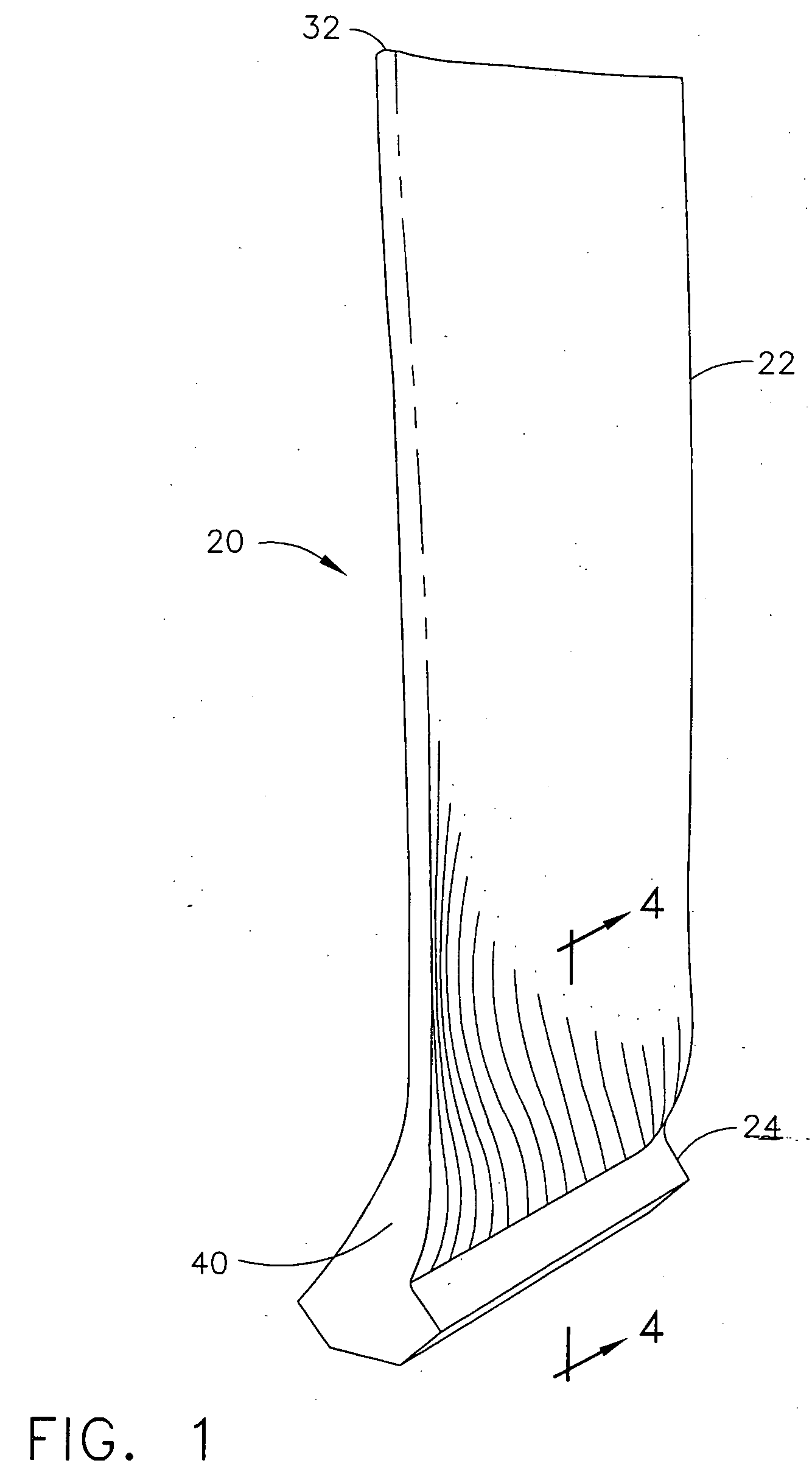
[0027]FIG. 1 depicts an exemplary aircraft engine LPT blade 20. In this illustration a turbine blade 20 comprises a ceramic matrix composite material. The turbine blade 20 includes an airfoil 22 against which the flow of hot exhaust gas is directed. The turbine blade 20 is mounted to a turbine disk (not shown) by a dovetail 24 that extends downwardly from the airfoil 22 and engages a slot of similar geometry on the turbine disk. The LPT blade of the present invnetion does not have an integral platform. A separate platform is provided to minimize the exposure of the dovetail to hot gases of combustion. The airfoil may be described as having a root end 40 and an oppositely disposed tip end 32.

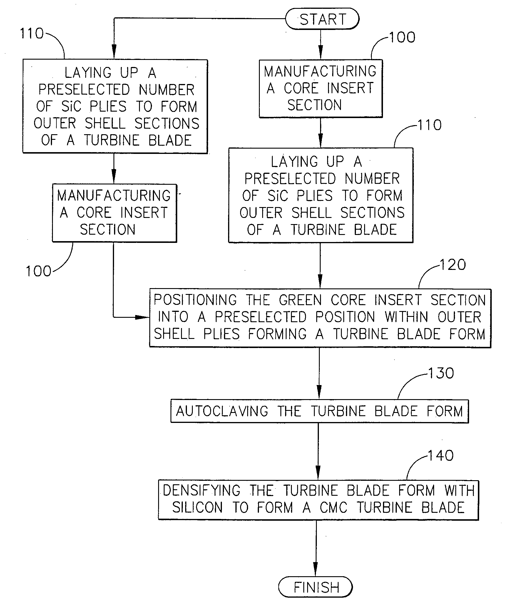
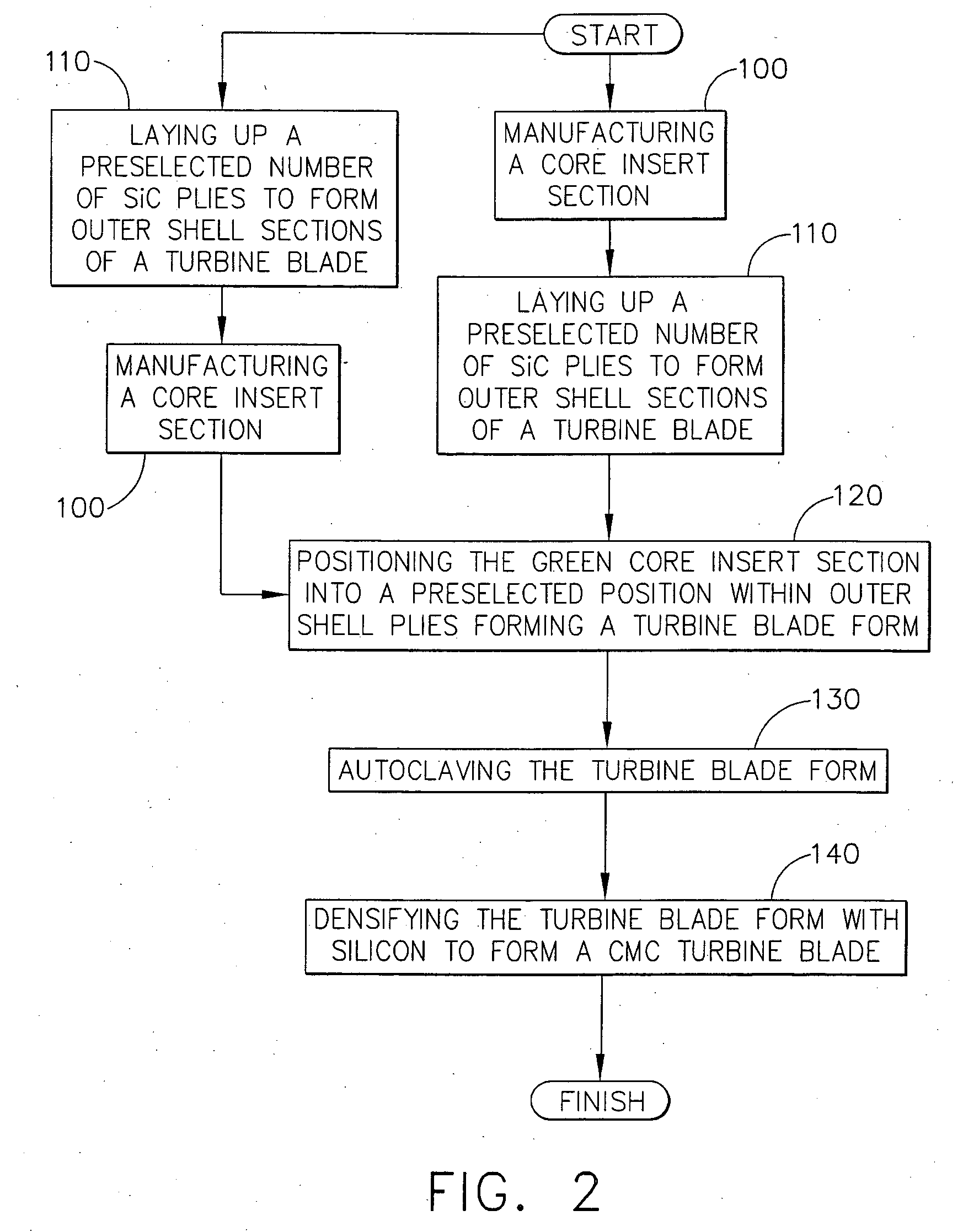
[0028]FIG. 2 is a flow chart illustrating a method of manufacture of a CMC turbine blade of the present invention using a method of silicon carbide-silicon carbide CMC manufacture known as a “prepreg” melt infiltration process (prepreg MI). Initially, outer shell SiC preforms are manufactured us...


PUM

PropertyMeasurementUnit
volume percentaaaaaaaaaa
porosityaaaaaaaaaa

Abstract

The present invention is a hybrid ceramic matrix composite turbine engine component comprising an outer shell section(s) and an inner core section(s), wherein the outer shell section(s) and the inner core section(s) were bonded together using an MI process. The outer shell section(s) comprises a SiC/SiC material that has been manufactured using a process selected from the group consisting of a slurry cast MI process and a prepreg MI process. The inner core section(s) comprises a material selected from the group consisting an Si/SiC composite material and a monolithic ceramic material. The Si/SiC composite material may be manufactured using the Silcomp process. The present invention may be a high pressure turbine blade, a high pressure turbine vane, a low pressure turbine blade, or a low pressure turbine vane. The present invention is also a method of manufacturing a hybrid ceramic matrix composite turbine engine component.

Description

FIELD OF THE INVENTION [0001] The present invention relates generally to ceramic matrix composite turbine engine components, and more particularly, to a hybrid ceramic matrix composite turbine blade. BACKGROUND OF THE INVENTION [0002] In order to increase the efficiency and the performance of gas turbine engines so as to provide increased thrust-to-weight ratios, lower emissions and improved specific fuel consumption, engine turbine are tasked to operate at higher temperatures. As the higher temperatures reach and surpass the limits of the material comprising the components in the hot section of the engine and in particular the turbine section of the engine, new materials must be developed. [0003] As the engine operating temperatures have increased, new methods of cooling the high temperature alloys comprising the combustors and the turbine airfoils have been developed. For example, ceramic thermal barrier coatings (TBCs) were applied to the surfaces of components in the stream of t...

Claims


Application Information

Patent Timeline
Patent Type & Authority Applications(United States)
IPC IPC(8): B32B18/00F01D1/02F01D5/28F01D9/02F02C7/00
CPCB32B18/00C04B2237/368B32B2315/02C04B35/565C04B2235/428C04B2235/5244C04B2235/80C04B2237/365F01D5/282F01D5/284Y02T50/67Y02T50/672F05D2300/2261F05D2300/603C04B35/62863C04B35/62868C04B35/62871C04B35/62873C04B2235/422C04B2235/5248C04B2235/5256C04B2235/5268C04B2235/616C04B2237/38C04B2237/61C04B2237/361C04B2237/363B32B2311/22Y02T50/60
Inventor CARPER, DOUGLAS MELTONSUBRAMANIAN, SURESHJENDRIX, RICHARD WILLIAMSTEIBEL, JAMES DALE
Owner GENERAL ELECTRIC CO
Why Eureka
Try Eureka