
Positioning template

a technology of positioning template and positioning frame, which is applied in the field of positioning template, can solve the problems of difficult and time-consuming task of hanging decorations in a home and/or office, difficulty in adjusting the position of the object, and difficulty in adjusting the position,

Active Publication Date: 2008-09-09
DEANGELIS MORRIS NANCY
View PDF14 Cites 28 Cited by
  • Summary
  • Abstract
  • Description
  • Claims
  • Application Information

AI Technical Summary

Benefits of technology

[0015]It is another object of the present invention to provide a method including the step of removing the anchoring mechanism along with the positioning template, properly securing the anchoring mechanism to the supporting surface and hanging the object to be hung via the mounting device.

Problems solved by technology

The art of hanging decorations in a home and / or office can be a challenging and time-consuming task.
Problems can easily arise from the traditional approach.
For example, the object to be hung could be rather large and / or heavy and cannot be lifted by one individual.
Using estimations will leave the user with some uncertainties, which could cause the decoration to be hung in a manner that is not intended by the individual.
If, however, another individual needs to be found to aid in the task, that can add to the total time to complete the task.
Another commonly occurring problem is marking the location of the anchoring device.
Because the decoration's support, which will engage the anchoring device, is commonly located behind the decoration itself, such as a painting, defining the correct location of the wall-anchoring device can be difficult.
It generally requires precise measurements and can be a time consuming task.
If the estimated location is incorrect, the supporting surface is left with an undesirable marking.
However, these prior efforts have shortcomings ranging from difficulty in use to leaving undesirable adhesives on the surface.
Additionally, these prior efforts lack flexibility to provide for reconfiguration for use with a multitude of decorations of different size and shape.

Method used


Image

  • Positioning template
  • Positioning template
  • Positioning template

Examples


Embodiment Construction

[0021]The detailed embodiments of the present invention are disclosed herein. It should be understood, however, that the disclosed embodiments are merely exemplary of the invention, which may be embodied in various forms. Therefore, the details disclosed herein are not to be interpreted as limiting, but merely as the basis for the claims and as a basis for teaching one skilled in the art how to make and / or use the invention.

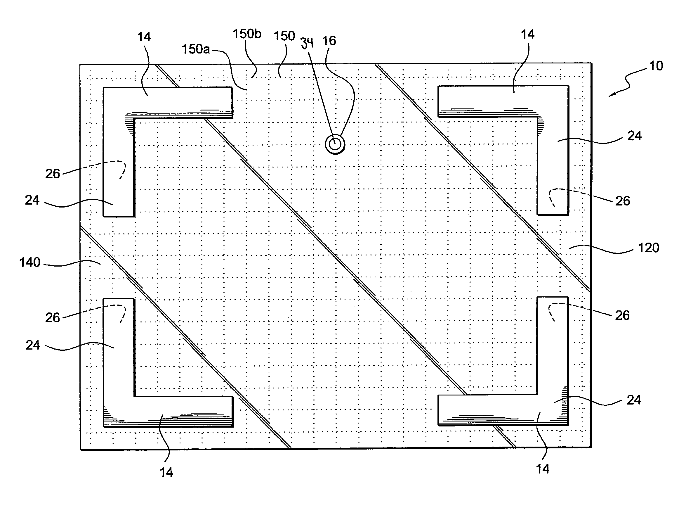
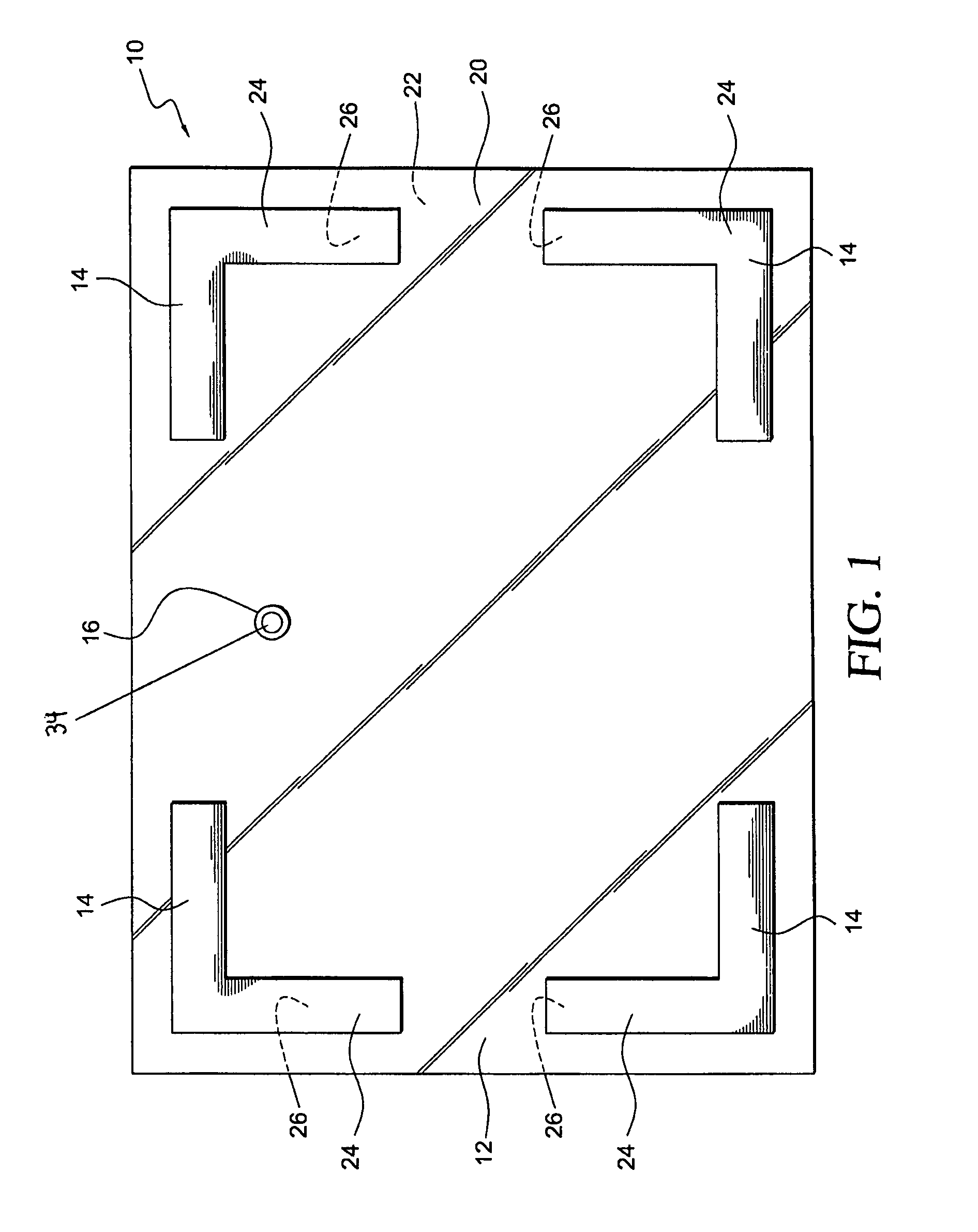
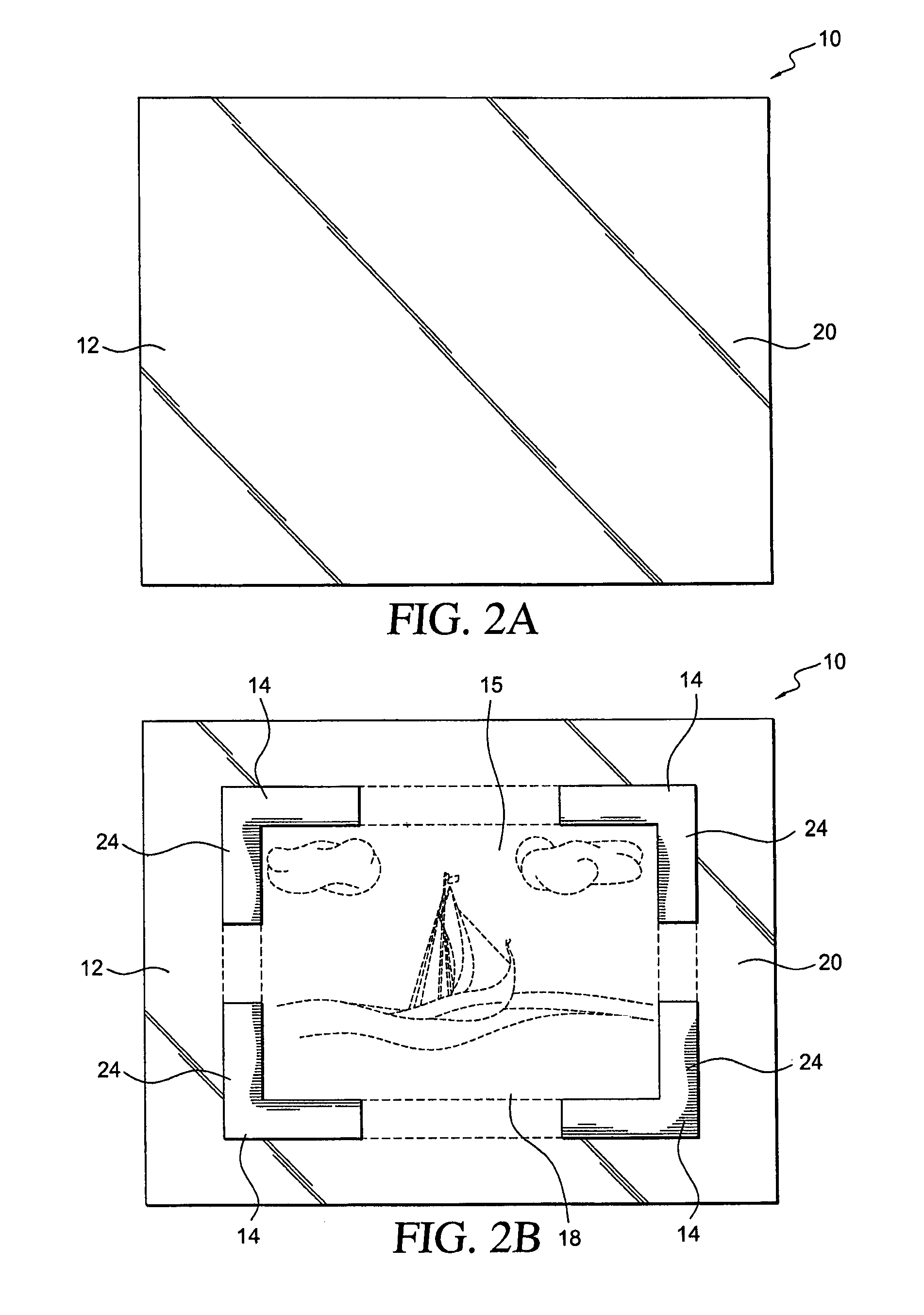
[0022]With reference to the various figures, a positioning template 10 is disclosed. The positioning template 10 aids users in hanging objects on various supporting surfaces 32 (for example, a framed picture 18 upon a wall 32 as shown in FIG. 2F). The positioning template 10 includes an electrostatically active template backing 12 having a front surface 20 and a rear surface 22. The positioning template 10 also includes a plurality of perimeter markers 14 shaped and dimensioned for selective placement on the front surface 20 of the template backing 12 in a manner...


PUM


Abstract

A positioning template for use in aiding in the hanging of objects on various supporting surfaces includes an electrostatically active template backing having a front surface and a rear surface, a plurality of perimeter markers shaped and dimensioned for releasable selective placement on the front surface of the template backing in a manner representing outer dimensions of an object to be hung, and a hole marker shaped and dimensioned for releasable selective placement on the front surface of the template backing to indicate a desired position of a hole for an anchoring device.

Description

BACKGROUND OF THE INVENTION[0001]1. Field of the Invention[0002]The invention relates to a positioning template. More particularly, the invention relates to a positioning template that uses an electrostatic material in conjunction with movable markers to provide a user with a visual representation of an object to be hung on a wall, or other flat surface.[0003]2. Description of the Related Art[0004]The art of hanging decorations in a home and / or office can be a challenging and time-consuming task. The task as traditionally performed requires at least two individuals; one to hold the decoration against the supporting surface (for example, the wall), while the other individual identifies the most appealing location for the object and marks the location for the anchoring device on the supporting surface. The anchoring device is then secured to the supporting surface at the point that was marked and the decoration is hung from it.[0005]Problems can easily arise from the traditional appro...

Claims


Application Information

Patent Timeline
IPC IPC(8): G01D21/00
CPCA47G1/205
Inventor DEANGELIS-MORRIS, NANCY
Owner DEANGELIS MORRIS NANCY
Learn More