Curtain clip

a technology of clips and clips, applied in the field of clips, can solve the problems of wasting time, creating gaps, and wasting threading time of rings on the rods, and achieving the effect of reducing the number of clips

Inactive Publication Date: 2015-03-19
EX CELL HOME FASHIONS
View PDF5 Cites 7 Cited by
  • Summary
  • Abstract
  • Description
  • Claims
  • Application Information

AI Technical Summary

Benefits of technology

[0010]In other embodiments the aperture is offset from said central location of said top. The bottom may be round or squared. Each protrusion may be provided with a curvature. The unibody member may be made from a material selected from the group consisting of polypropylene, polystyrene, acrylic, and spring steel. In some embodiments one or more of the first or second sides is provided with an embellishment disposed on or integral with an outer surface of the first or second side.
[0011]In some embodiments each shoulder is provided with a bead disposed on an inner surface thereof. In some embodiments each shoulder is provided with a depression disposed on an inner surface thereof, and a bearing configured to fit within an individual depression is placed within each depression and secured in place with a bushing to properly secure said bearing to said unibody member and enable free motion thereof.

Problems solved by technology

Current systems for hanging curtains using ring systems share a common disadvantage.
The threading of the rings on the rod is time consuming.
Moreover, when hooks are used the curtain may easily lift out of the hook during use, creating a gap and requiring maintenance.
Moreover, inserting hooks into rings is also a time-consuming exercise, and it may be particularly difficult for people who are unable to use both hands or who are not able to hold their hands above their head for long periods of time.
Many clips may not be useful because their opening points downward, allowing the curtain to slip from the clip and fall.

Method used


Image

  • Curtain clip
  • Curtain clip
  • Curtain clip

Examples


Embodiment Construction

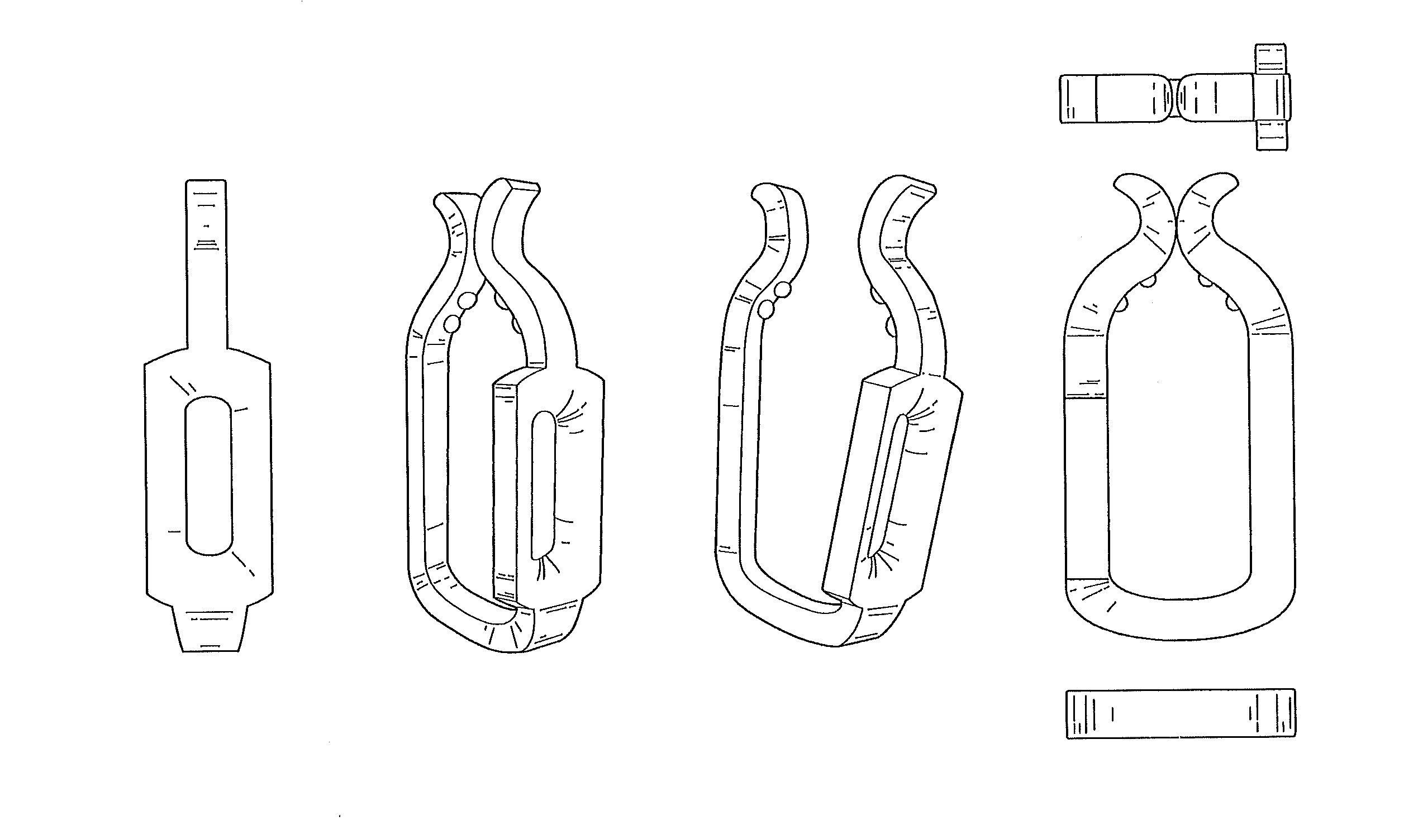
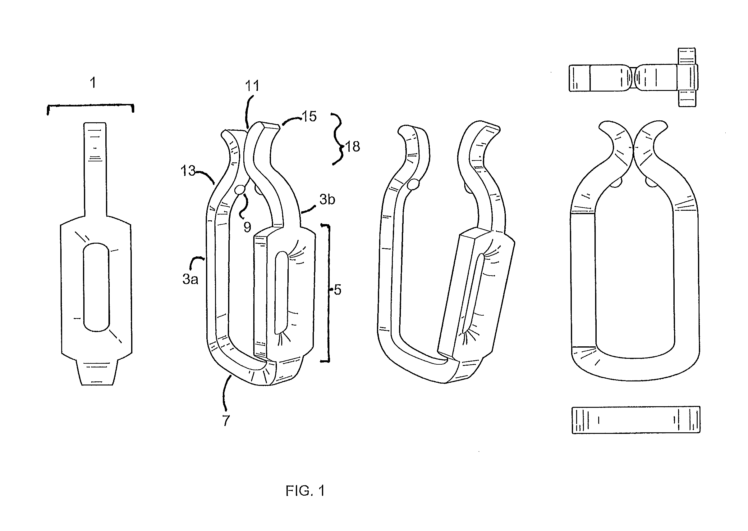
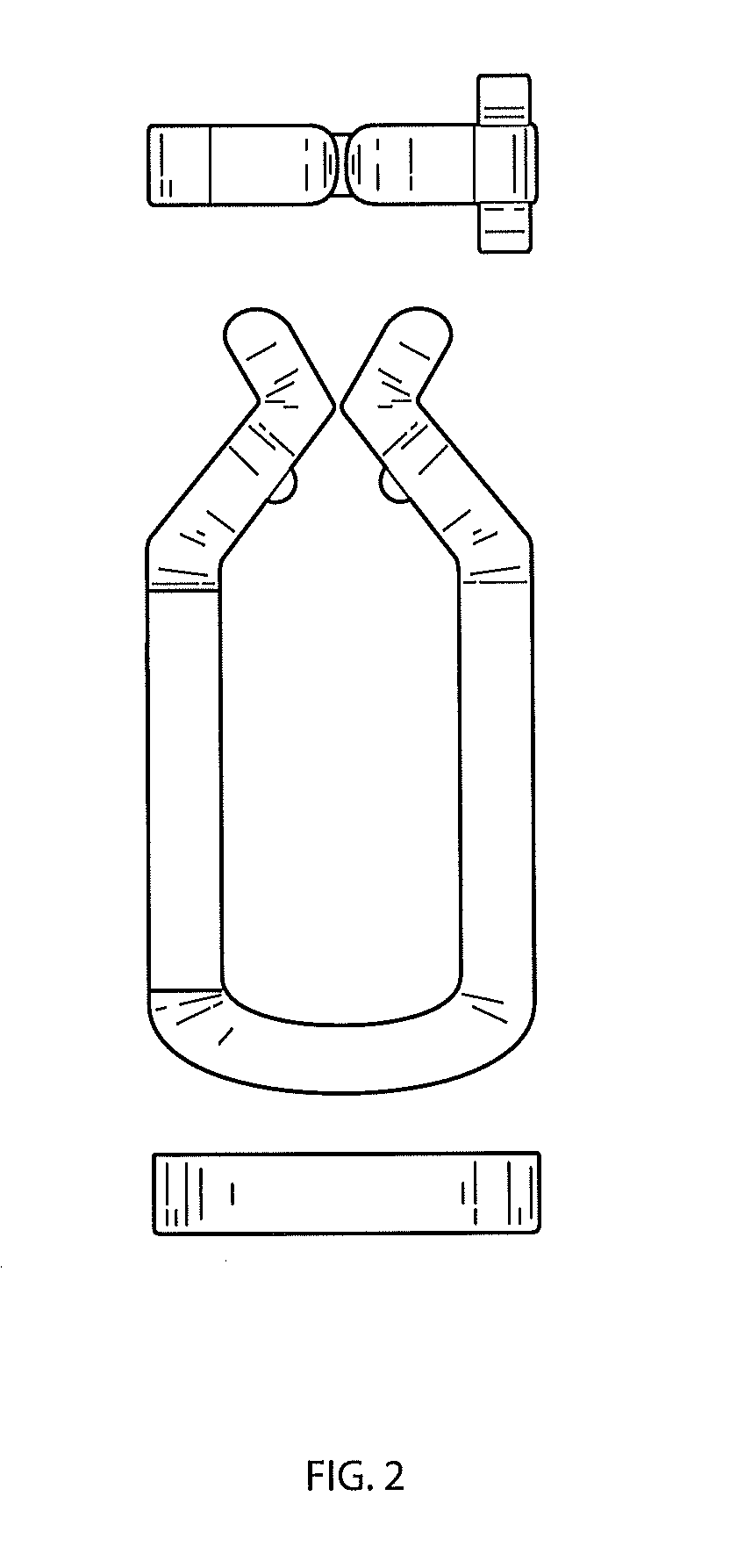
[0022]We provide clips 1 for use in retaining curtains 19 without the need for separate hooks. Embodiments of the invention comprise at least one clip 1 having a bottom 7, a first side 3a, a second side 3b, and a top 18. Each clip 1 may have a shape including but not limited to approximately circular, oval, rectangular, hexagonal, or teardrop-shaped. Often the place where the sides 3a, 3b meet the bottom 7 is rounded. Where the sides 3a, 3b meet the top 18 may have sufficient curvature to be described as “shoulders”13 of the clip 1.

[0023]A central portion of the top 18 of the clip 1 has an aperture 11 through which a curtain eyelet 21 and a curtain rod 17 may be placed. When in use, the top 18 of the clip 1, and therefore the aperture 11, is on the side of the curtain rod 17 opposite the side from which the curtain 19 depends. In some embodiments, however, the clip 1 is shaped and / or weighted so that the aperture 11 is offset from the central portion of the top 18.

[0024]Embodiments ...


PUM


Abstract

We provide a securement apparatus or clip including a flexible unibody member that allows two sides of the clip to be separated, allowing the clip to be placed around a rod to support a curtain. Each part of the clip that is in contact with the rod includes a point of minimal contact with the rod, designed to reduce friction and to help maintain the clip on the rod.

Description

CROSS-REFERENCE TO RELATED APPLICATIONS[0001]This application claims priority to U.S. Provisional Patent Application No. 61 / 878,735, filed on Sep. 17, 2013. That application is incorporated by reference herein.BACKGROUND OF THE INVENTION[0002]1. Field of the Invention[0003]Embodiments of the invention relate to curtain clips that may be used to retain shower curtains, decorative curtains, and the like on a rod.[0004]2. Background of the Related Art[0005]Curtains are in common use for a number of purposes throughout the home. They may be used for privacy, to block sun, or to prevent egress of water from a shower or bath. These curtains normally depend from a rod.[0006]Many curtains, especially bath or shower curtains, include integral rings or eyelets through which the rod may be threaded to allow the shower curtain to depend directly from the rod. In other cases a series of rings are placed on a rod, and hooks depend from or are integral with these rings. The hooks are then mated wi...

Claims


Application Information

Patent Timeline
Patent Type & Authority Applications(United States)
IPC IPC(8): A47H15/04A47H23/00A47H13/01
CPCA47H15/04A47H23/00A47H13/01Y10T24/51
Inventor GLAZE, AKEEM PIERREDAVIS, JEREMYSMITH, NOELLE
Owner EX CELL HOME FASHIONS
Why Eureka
Try Eureka