
Air admittance valve assembly

a technology of air admittance valve and assembly, which is applied in the direction of mechanical equipment, transportation and packaging, functional valve types, etc., to achieve the effect of reliable and effective venting, efficient movement and direct air

Active Publication Date: 2008-09-09
OATEY CO
View PDF4 Cites 5 Cited by
  • Summary
  • Abstract
  • Description
  • Claims
  • Application Information

AI Technical Summary

Benefits of technology

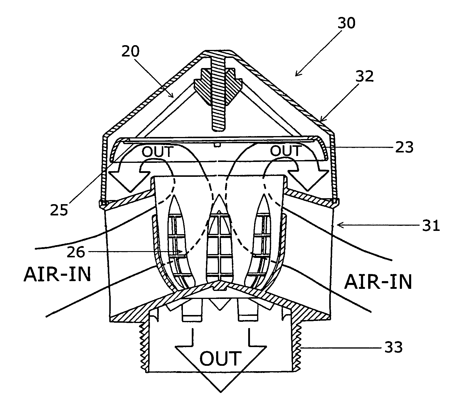
The present invention provides an air admittance valve assembly for low pressure venting into a closed system, such as a plumbing drain and waste system. The valve is designed to allow air to flow in and out of the system in a controlled and efficient manner. The valve is responsive at low pressures and can comply with various plumbing codes and regulatory agencies. The valve body structure allows for radial air inflow and efficient airflow through and out of the valve body. The technical effects of this invention include improved air flow control, responsiveness at low pressures, and compliance with plumbing codes and regulations.

Problems solved by technology

Secondly, directed inflow patterns are provided by upwardly angled inlet ports.
Thirdly, an air deflector shield is placed around the sealing membrane providing increased seal opening at each flow rate of air compared to structures not incorporating an air deflector shield.

Method used


Image

  • Air admittance valve assembly
  • Air admittance valve assembly
  • Air admittance valve assembly

Examples


Embodiment Construction

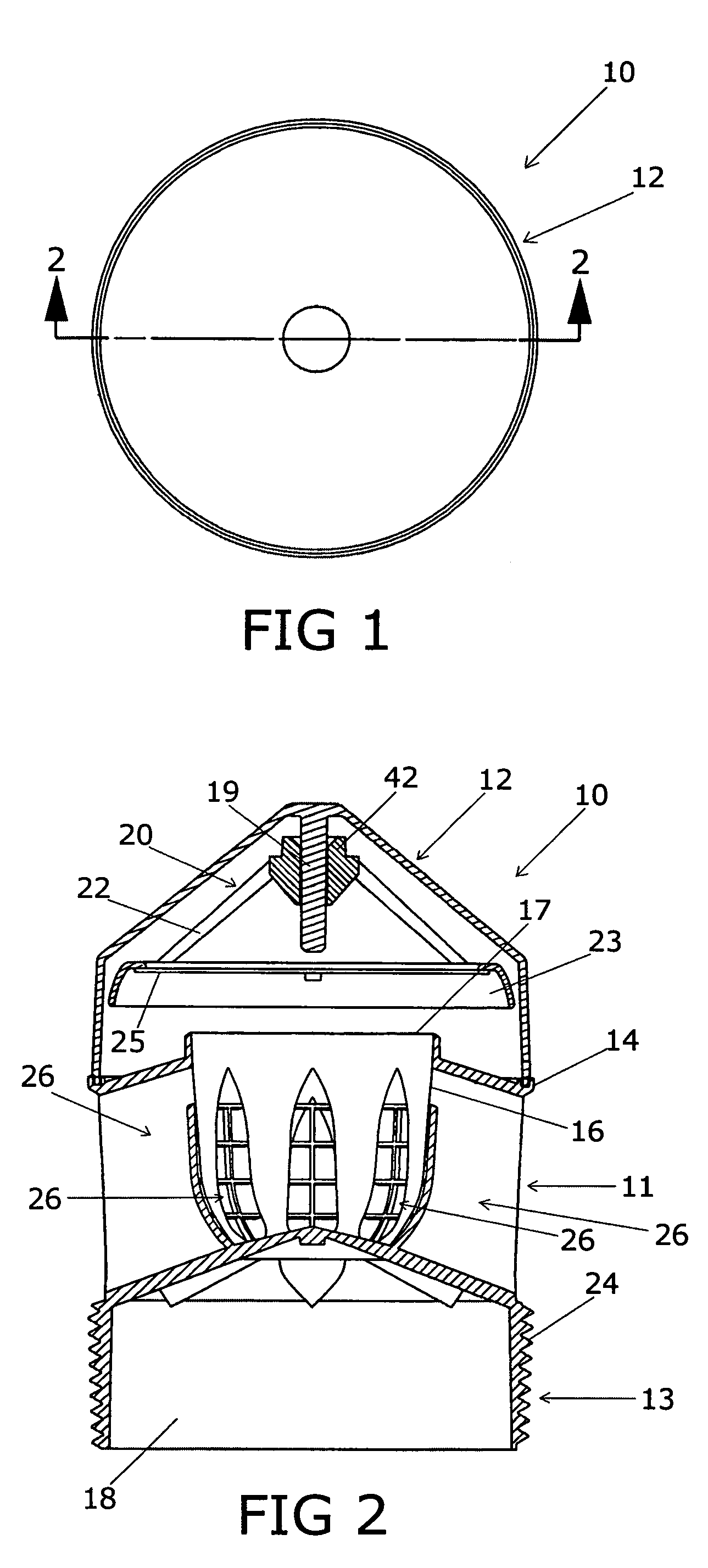
[0036]Referring to FIGS. 1 and 2, a one-way valve assembly 10 is shown comprising a valve body 11 and a cap member 12 mounted thereon. The valve body 11 has a bottom connecting portion 13 which by means of pipe threads 24, for example, may be connected to a closed system, such as a plumbing system. The valve assembly 10 is constructed and arranged for connection to the vent portion of a drain-waste-vent (DWV) plumbing system to permit ambient air to enter the system during negative pressure or vacuum conditions and to seal the drainage system during positive pressure conditions to thereby prevent gases from entering the ambient environment. The valve assembly 10 may also be utilized in other closed systems requiring one-way venting from the ambient environment under low differential pressures, i.e., in the order of 0.3 inches of water pressure or 0.01 psi.

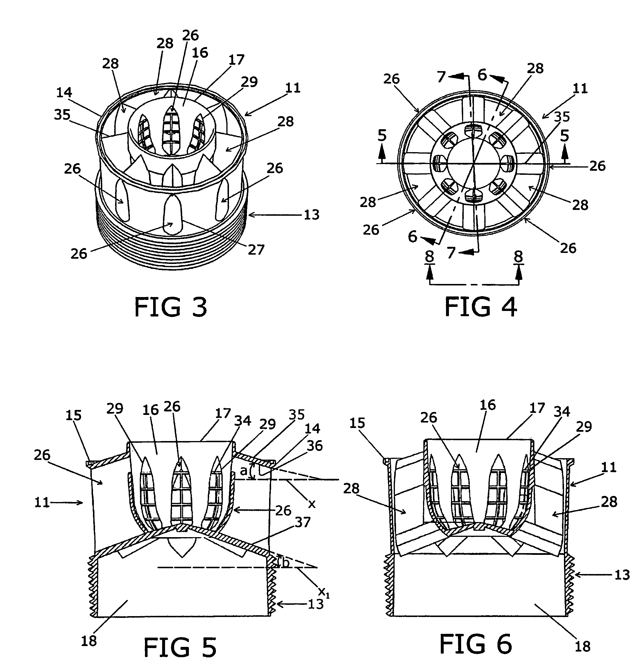
[0037]Referring further to FIGS. 3-6 the valve body member 11 of the one-way valve assembly 10 is further shown to comprise a val...


PUM


Abstract

A one directional flow valve assembly for a fluid system. The valve assembly is comprised of a valve body having an internal valve chamber in communication with the ambient environment and a valve seat arrangement. The assembly further has a cap structure with means to position and align a sealing member with respect to the valve seat. A flexible elastomeric sealing diaphragm may be utilized and which is under tension when the sealing diaphragm is in a sealing configuration. The sealing member has a peripheral deflection shield to direct ambient fluid through the valve body. A carrier plate structure may be provided to position the sealing member and deflection shield with respect to the valve seat arrangement to operate the valve assembly.

Description

[0001]This application claims the benefit of U.S. Provisional Patent Application Ser. No. 60 / 588,557, having the filing date of Jul. 15, 2004.BACKGROUND OF THE INVENTION[0002]This invention relates generally to a one directional flow valve assemblies for fluid systems and particularly to assemblies which more efficiently permit the ambient environment to equalize negative pressure differentials within the fluid system while preventing positive pressure gases from escaping into the ambient environment. The present invention particularly provides improved and efficient airflow characteristics which are for air admittance valve assemblies. These valve assemblies are constructed and arranged to provide an automatic one-way valve structure operative in low pressure differential environments such as in the drain portion of a plumbing system. The valve assemblies of the invention provide responsive and sensitive air inlet valve structures for, but not restricted to, indoor use environments...

Claims


Application Information

Patent Timeline
Patent Type & Authority Patents(United States)
IPC IPC(8): F16K21/04F16K15/14
CPCF16K15/08Y10T137/7897Y10T137/7913Y10T137/7918
Inventor STONE, RICHARD T.
Owner OATEY CO
Learn More