Vehicle pathway vision system having in-path delineation reticle

a path vision and vehicle technology, applied in the field of vehicle path vision system, can solve the problems of difficulty in determining whether a displayed object is in-path or out-of-path, how far the object is from the vehicle, etc., and achieves the effect of reliably identifying the range of displayed objects, reducing transmissivity, and easy and reliably distinguishing between in-path and out-of-path objects in the displayed scen

Active Publication Date: 2008-09-09
APTIV TECH LTD
View PDF10 Cites 64 Cited by
  • Summary
  • Abstract
  • Description
  • Claims
  • Application Information

AI Technical Summary

Benefits of technology

[0003]The present invention is directed to vehicle vision system for displaying an image of a scene in the direction of the vehicle pathway, where the displayed image includes a reticle that visually delineates the in-path portion of the scene. The reticle is preferably formed by a reticle array disposed between a video camera chip and a lens, the array including a conical or frustro-conical region of substantially un-attenuated light transmissivity surrounded by a region of perceptibly attenuated light transmissivity, such that in-path portions of the displayed image are substantially without attenuation and out-of-path portions of the displayed image are perceptibly attenuated. As a result, the driver can easily and reliably distinguish between in-path and out-of-path objects in the displayed scene. The reticle array preferably also includes a number of reduced transmissivity or opaque lines traversing its conical or frustro-conical region to produce a series of receding stadia lines in the in-path portion of the displayed image, enabling the driver to reliably discern the range of displayed objects.

Problems solved by technology

While it is generally desirable to display a wide field-of-view (FOV) that includes both in-path and out-of-path objects, the driver may have difficulty determining whether a displayed object is in-path or out-of-path, and how far the object is from the vehicle.

Method used


Image

  • Vehicle pathway vision system having in-path delineation reticle
  • Vehicle pathway vision system having in-path delineation reticle
  • Vehicle pathway vision system having in-path delineation reticle

Examples


Embodiment Construction

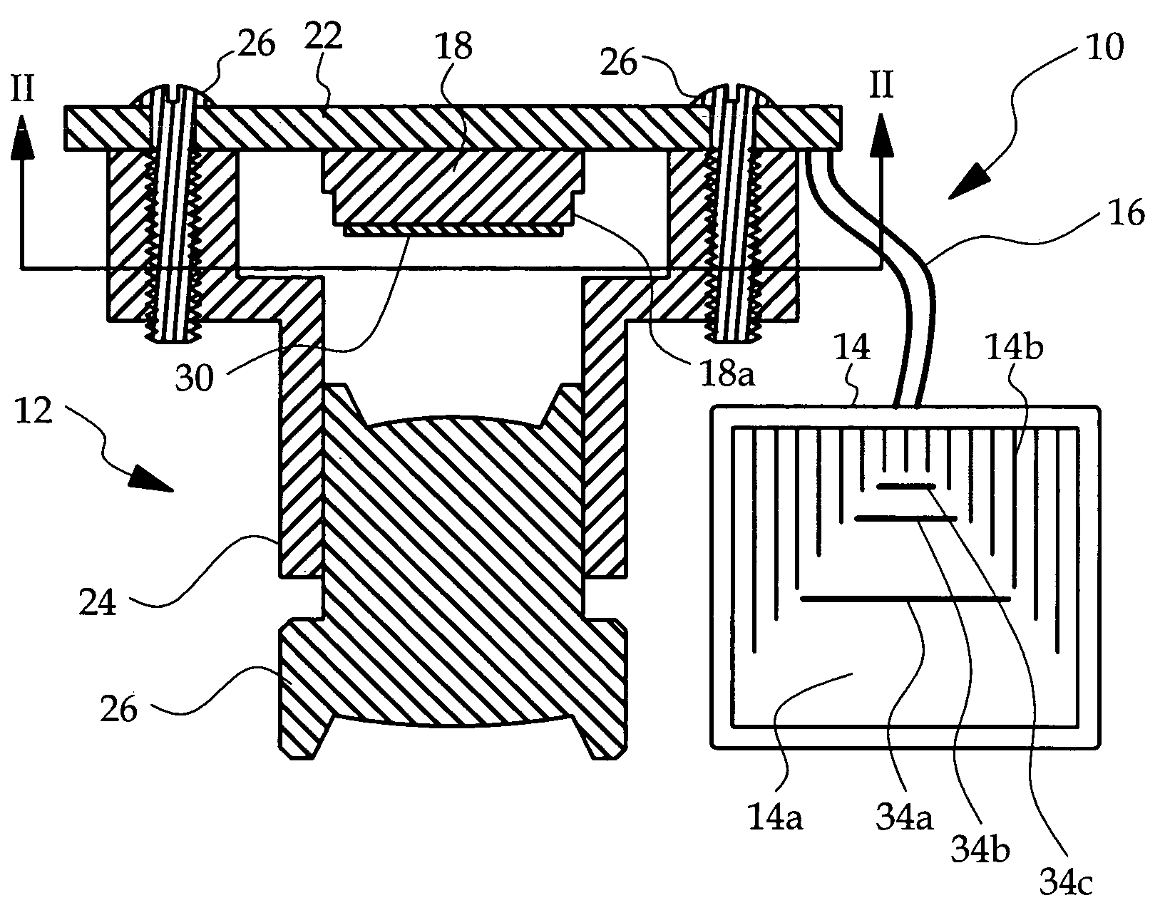
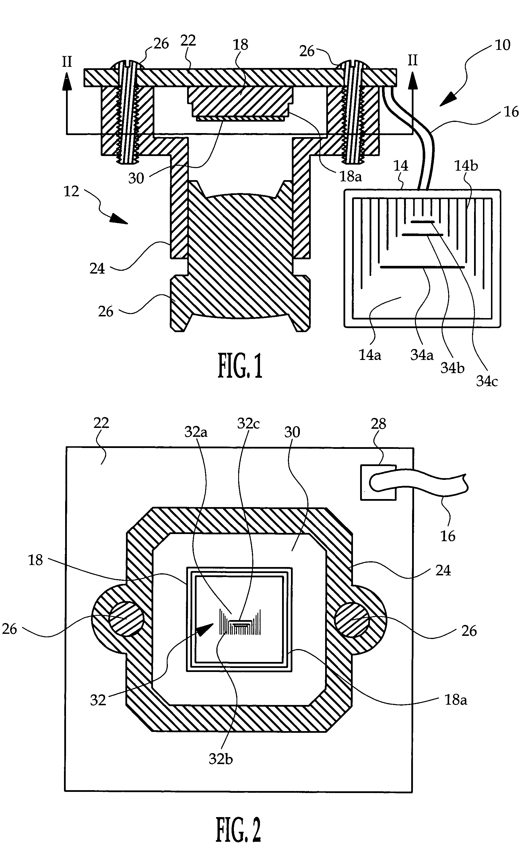
[0008]The vision system of the present invention is disclosed in the context of a back-up aid for a motor vehicle, where the driver views a video image of a scene along the rearward travel path of the vehicle to determine if the travel path is obstructed. Of course, other applications are also possible, and the system may be part of a more sophisticated control such as a driver warning control or a collision avoidance control.

[0009]Referring to FIG. 1, the vision system is generally designated by the reference numeral 10, and fundamentally includes a camera assembly 12 and a display device 14 (such as a conventional flat-panel display) coupled to the camera assembly 12 by a video cable 16. The camera assembly 12 may be mounted, for example, in a central rearward portion of the vehicle, such as in the vicinity of a center-high-mounted-stop-lamp (CHMSL) or the like, whereas the display device 14 will typically be mounted in the vehicle instrument panel or in the vicinity of an interio...


PUM


Abstract

A vehicle vision system displays a vehicle pathway image that includes a reticle for visually identifying the in-path portion of the image. A reticle array is disposed between a video camera chip and a lens, and includes a conical or frustro-conical region of substantially un-attenuated light transmissivity surrounded by a region of perceptibly attenuated light transmissivity, such that in-path portions of the displayed image are substantially unchanged and out-of-path portions of the displayed image are perceptibly attenuated. The reticle array may also include a number of reduced transmissivity lines traversing its conical or frustro-conical region to produce a series of receding stadia lines in the in-path portion of the displayed image, enabling the driver to reliably discern the range of displayed objects.

Description

TECHNICAL FIELD[0001]The present invention relates to a pathway vision system for a vehicle, and more particularly to a system that visually distinguishes between in-path and out-of-path regions of a displayed view.BACKGROUND OF THE INVENTION[0002]Vehicle pathway vision systems use one or more video cameras to display video images in the direction of the forward or reverse pathway of the vehicle to help the driver maneuver the vehicle in a safe manner. The displayed image can be used for vision enhancement during poor lighting conditions, or to present a view that is otherwise restricted or hidden. For example, a reverse pathway image can be displayed as a back-up aid. While it is generally desirable to display a wide field-of-view (FOV) that includes both in-path and out-of-path objects, the driver may have difficulty determining whether a displayed object is in-path or out-of-path, and how far the object is from the vehicle. Accordingly, what is needed is a pathway vision system t...

Claims


Application Information

Patent Timeline
Patent Type & Authority Patents(United States)
IPC IPC(8): H04N7/18B60K35/00B60Q1/48B60Q1/52B60R1/00G01B11/00G01C3/22G08G1/04
CPCB60R1/00G01C3/22B60R2300/305
Inventor RAY, MICHAEL S.TAYLOR, RONALD M.NOHNS, DENNIS C.
Owner APTIV TECH LTD
Why Eureka
Try Eureka