
Tool-free tire traction device

a technology of tire traction and tool-free tires, which is applied in the direction of non-skid devices, wheels with spade lugs, vehicle components, etc., can solve the problems of inconvenient or nearly impossible attachment of prior art devices to vehicle wheels or tires, and it is difficult to move the device from its stationary position using only the engine power of the stuck vehicle, etc., to achieve the effect of convenient and quick attachment and removal of the vehicle wheel and tir

Inactive Publication Date: 2008-09-23
CHAISSON JR SIDNEY J
View PDF13 Cites 11 Cited by
  • Summary
  • Abstract
  • Description
  • Claims
  • Application Information

AI Technical Summary

Benefits of technology

[0007]Therefore, one object of the present invention is to provide a tool-free tire traction device which is easily and quickly attached to and detached from a vehicle wheel and tire.
[0008]It is also an object of the present invention to provide a tool-free tire traction device which is small and portable.
[0009]A further object of the present invention is to provide a tool-free tire traction device which provides substantially greater traction when deployed.

Problems solved by technology

With little or no traction between the tire and the surrounding medium, it can be exceptionally difficult to move it from its stationary position using only the engine power of the stuck vehicle.
The problem with this technique is that the traction is only provided instantaneously, and the mats or boards are forcibly expelled from contact with the tire upon rotation of the tire.
Many such prior art devices are quite inconvenient or nearly impossible to attach to the vehicle wheel or tire when the vehicle has become mired in mud, snow, ice, sand or the like.
Frequently the vehicle operator gets soiled while attaching the device, particularly if the vehicle must be raised by a jack in order to install the traction device.
Furthermore, rain, snow or other dampness usually reduces the coefficient of friction between prior art traction devices and the tire, permitting the traction device to slip circumferentially about the tire during use.
However, most of these devices are rather cumbersome to use and require a fastening arrangement or specific tools to hold the device onto the tire.

Method used


Image

  • Tool-free tire traction device
  • Tool-free tire traction device
  • Tool-free tire traction device

Examples


Embodiment Construction

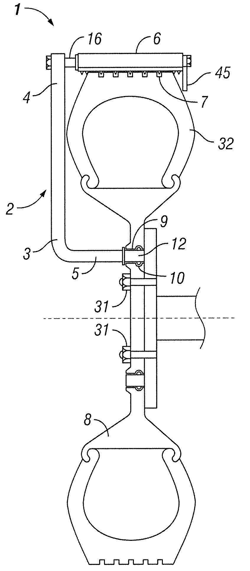
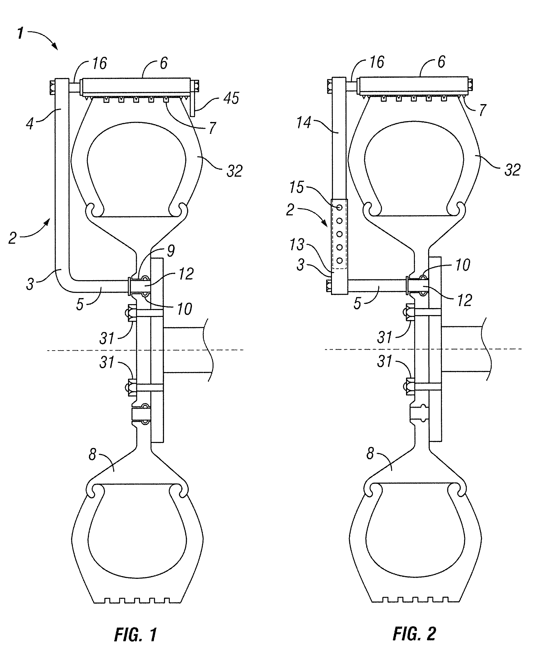
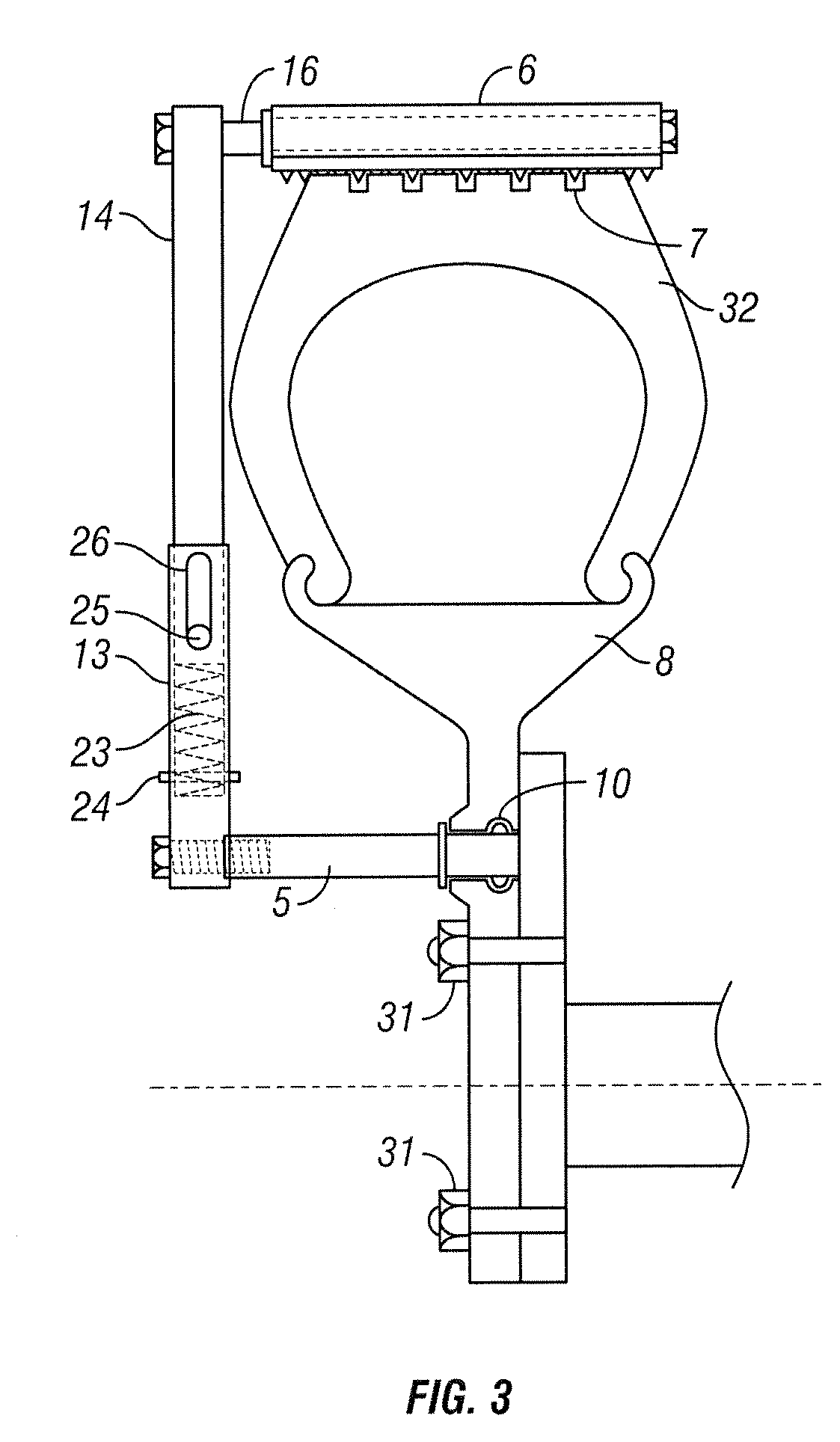
[0018]Turning now to FIG. 1, a preferred embodiment of a tool-free tire traction device in accordance with the present invention is shown. The traction device 1 generally comprises a support member 2 having a first end 3 and a second end 4; a connection member 5 extending from the first end 3 of the support member 2; a shaft 16 extending from the second end 4 of the support member 2; and a traction member 6 rotatably mounted to the shaft 16. Preferably, the traction member 6 further includes one or more tire-gripping devices 7.

[0019]With specific reference to the connection member 5, FIG. 2 depicts one alternative embodiment wherein the connection member 5 is a separate part attached by a common fastener to the first end 3 of the support member 2. The connection member 5 is adapted to matably engage a portion of the wheel 8. For example, the connection member 5 may be a simple pin 12 adapted for matable insertion into a specially formed mounting hole 9 on the wheel 8. A predetermine...


PUM


Abstract

A traction device for vehicle tires is provided for when the vehicle is stuck in mud, snow, ice or similar terrain, comprising an adjustable support member having a first end and a second end; a connection member extending from the first end of the support member, wherein the connection member is connectable to a wheel; a shaft extending from said second end of said support member; and a traction member rotatably mounted to the shaft, wherein the traction member includes one or more tire-gripping portions. A double-ended embodiment of the traction device is also disclosed for providing greater traction in appropriate situations.

Description

BACKGROUND OF THE INVENTION[0001]I. Field of the Invention[0002]The present invention relates generally to devices used to impart traction to vehicle tires for extraction of the vehicle from mud, snow, ice, sand or similar terrain, and more particularly to such devices which are portable and quickly attachable and detachable from the wheel.[0003]II. Background and Prior Art[0004]Since the invention of the automobile, drivers have invariably found themselves stuck in mud, snow, ice or sand. With little or no traction between the tire and the surrounding medium, it can be exceptionally difficult to move it from its stationary position using only the engine power of the stuck vehicle. Over the years, a range of techniques have been used in an attempt to overcome the situation. To this day, for example, coarse mats or wooden boards are often placed under the tire to provide some additional traction. The problem with this technique is that the traction is only provided instantaneously, a...

Claims


Application Information

Patent Timeline
Patent Type & Authority Patents(United States)
IPC IPC(8): B60C27/20B60C27/10
CPCB60C27/04
Inventor CHAISSON, JR., SIDNEY J.
Owner CHAISSON JR SIDNEY J
Learn More