Adjustable curved guideway for a conveyor and method for realising same

a conveyor and curved technology, applied in the direction of conveyors, conveyor parts, mechanical conveyors, etc., can solve the problem of not being able to achieve the same in curved sections

Inactive Publication Date: 2008-10-07
GEBO CERMEX CANADA
View PDF11 Cites 58 Cited by
  • Summary
  • Abstract
  • Description
  • Claims
  • Application Information

AI Technical Summary

Benefits of technology

[0011]Furthermore, there is disclosed a curved guideway assembly for use in an air conveyor for conveying articles having a variable width neck portion and suspended in the guideway by a flange immediately above the neck portion, The assembly comprises a pair of curved guides having substantially the same curve centre and defining a guideway width there between. At least one of the guides is an adjustable guide, the guides movable towards or away from one another such that the guideway width is adjustable between a first width, a second width and at least one intermediate width. In operation, the guideway width is adjusted such that the neck portion of the article being conveyed may move freely therein while remaining retained within the guideway by the flange.

Problems solved by technology

One drawback of such prior art devices arises when bottles with different neck diameters need to be conveyed on the same conveyor.
While it is fairly straightforward to move straight and parallel guide sections in and out to adjust the distance between them, doing the same in curved sections is not as simple as it is not only the guide's position that must change, but also its shape.
One drawback of the above prior-art devices is that they move only between two positions and therefore provide only for a small number of different guideway widths.
One challenge is therefore to move a curved guide section toward or away from its centre of curvature while at the same time adjusting its radius of curvature so that the guide's centre of curvature remains stationary.

Method used


Image

  • Adjustable curved guideway for a conveyor and method for realising same
  • Adjustable curved guideway for a conveyor and method for realising same
  • Adjustable curved guideway for a conveyor and method for realising same

Examples


Embodiment Construction

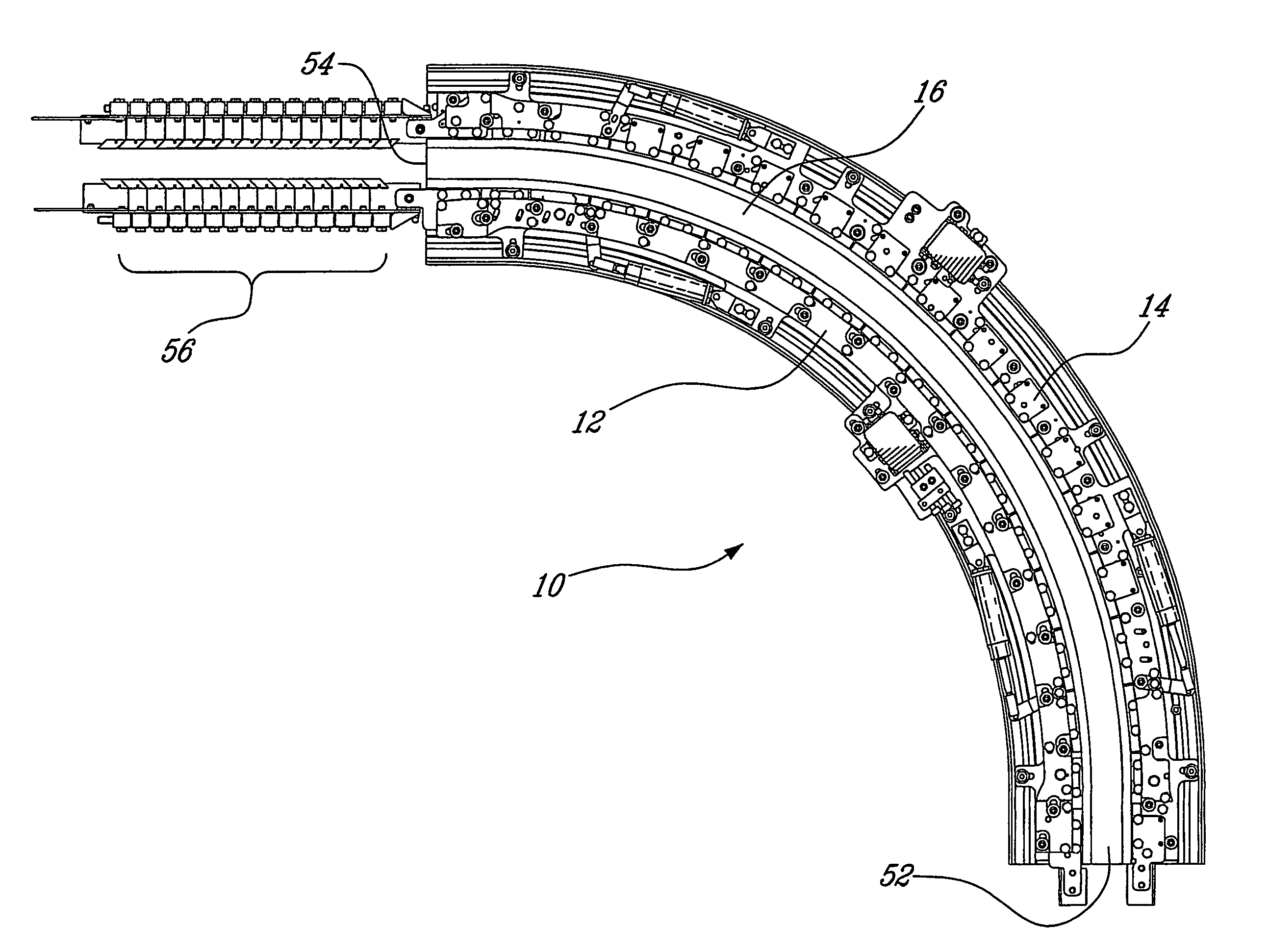
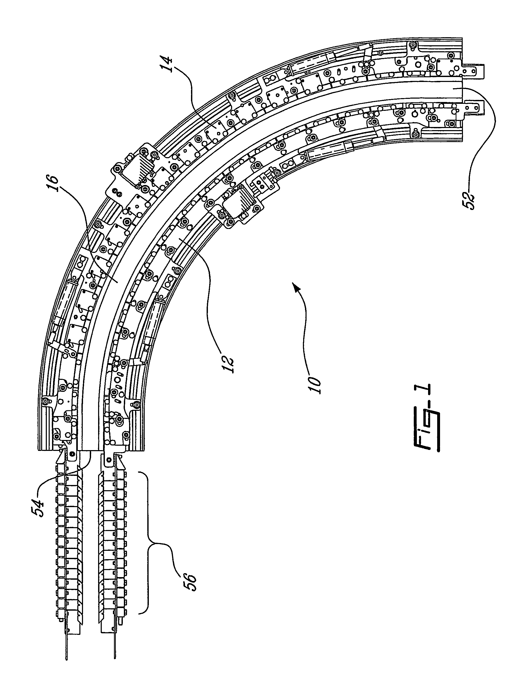
[0029]Referring now to FIG. 1, an adjustable curved guideway, generally referred to using the reference numeral 10, will now be described. In general, the various components of the adjustable curve 10 are manufactured from a rigid material suited for bending, drilling and the like such as stainless steel plate, aluminum, titanium and the like, with the various components being assembled together using suitable fastening techniques such as nut and bolts assemblies, welding or other bonding techniques.

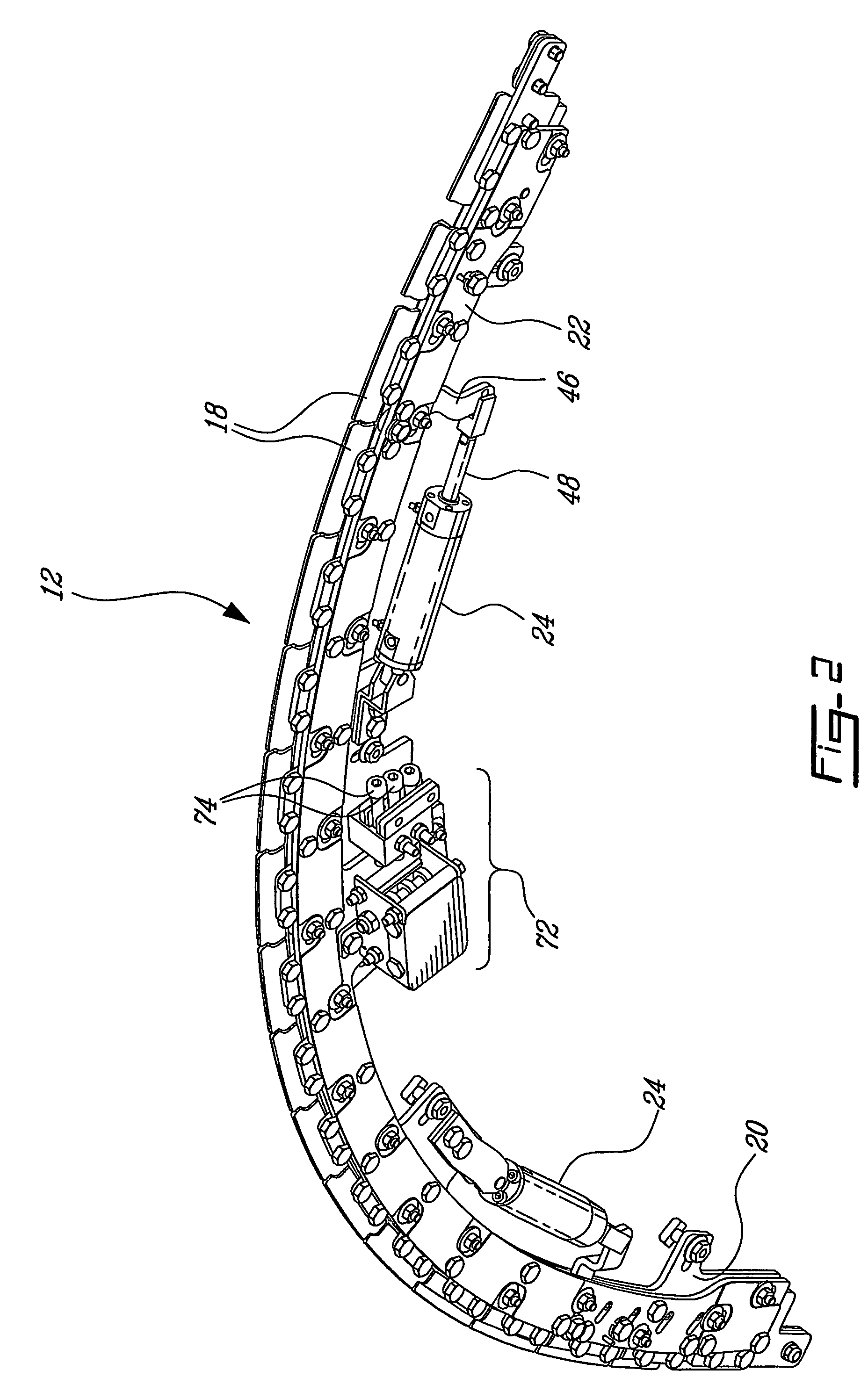
[0030]Still referring to FIG. 1, the curve 10 is comprised of inner curve section 12 and an outer curve section 14 which oppose one another and define a guideway 16 in between. Referring to FIG. 2, the inner curve section 12 (as well as the outer curve section 14) is comprised of a series of abutting segments as in 18 sandwiched between a first plate 20 and a second plate, 22. Illustratively, the first plate 20 is held securely by a supporting framework (not shown) and remains immoveable...


PUM


Abstract

An adjustable curved neck guide for a conveyor is disclosed. The guide comprises a plurality of segments mounted on first and second plates using a series of pin and slot assemblies. Each segment has first and second surfaces and a guide edge, the segments arranged end to end such that the guide edges define a curve having radius. As the second plate is moved relative to the first plate, the pins slide in the slots thereby moving the segments and changing the radius of curvature defined by the guide edges.

Description

CROSS REFERENCE TO RELATED APPLICATIONS[0001]This application claims priority to PCT application No. CA2004 / 000227 filed on Feb. 18, 2004 and published in English under PCT Article 21(2); in U.S. provisional application No. 60 / 447,693 filed on Feb. 19, 2003; and in Canadian application no. 2,419,562 filed on Feb. 18, 2003. All documents above are herein incorporated by reference.FIELD OF THE INVENTION[0002]The present invention relates to an adjustable curved guide for a conveyor and a method for realising the same. In particular, the present invention relates to a curved guide wherein the distance between the guides can be adjusted by increasing or decreasing the radius of curvature of the guides.BACKGROUND[0003]Air conveyors are commonly used to convey empty plastic bottles. The bottles are supported by a ring flange located between the containers' shoulder and the threaded part of the container's neck. The flange rests on a pair of opposing guides which in turn define a guideway ...

Claims


Application Information

Patent Timeline
Patent Type & Authority Patents(United States)
IPC IPC(8): B65G21/20B65G51/00B65G51/03B65G21/14
CPCB65G21/10B65G21/14B65G21/16B65G21/2072B65G51/035B65G2201/0247
Inventor RANGER, MICHEL
Owner GEBO CERMEX CANADA
Why Eureka
Try Eureka