Closed-loop rotational control of a brushless dc motor

a brushless dc motor and closed-loop technology, applied in the direction of motor/generator/converter stopper, dynamo-electric converter control, instruments, etc., can solve the problem that the interaction between the phase windings and the magnets is not sufficient to permit bemf control, and achieve faster and more efficient closed-loop acceleration of the motor, reducing the potential for inadvertent rotation of the motor

Inactive Publication Date: 2008-10-07
SEAGATE TECH LLC
View PDF34 Cites 39 Cited by
  • Summary
  • Abstract
  • Description
  • Claims
  • Application Information

AI Technical Summary

Benefits of technology

[0018]In this way, faster and more efficient closed-loop acceleration of the motor can be achieved, reducing the potential for inadvertently rotating the motor in the wrong direction and fluctuations in current consumption of the motor from a power supply.

Problems solved by technology

At lower intermediate motor velocities, the interaction between the phase windings and the magnets may be insufficient to permit bemf control to accelerate and maintain rotation of the motor.

Method used


Image

  • Closed-loop rotational control of a brushless dc motor
  • Closed-loop rotational control of a brushless dc motor
  • Closed-loop rotational control of a brushless dc motor

Examples


Embodiment Construction

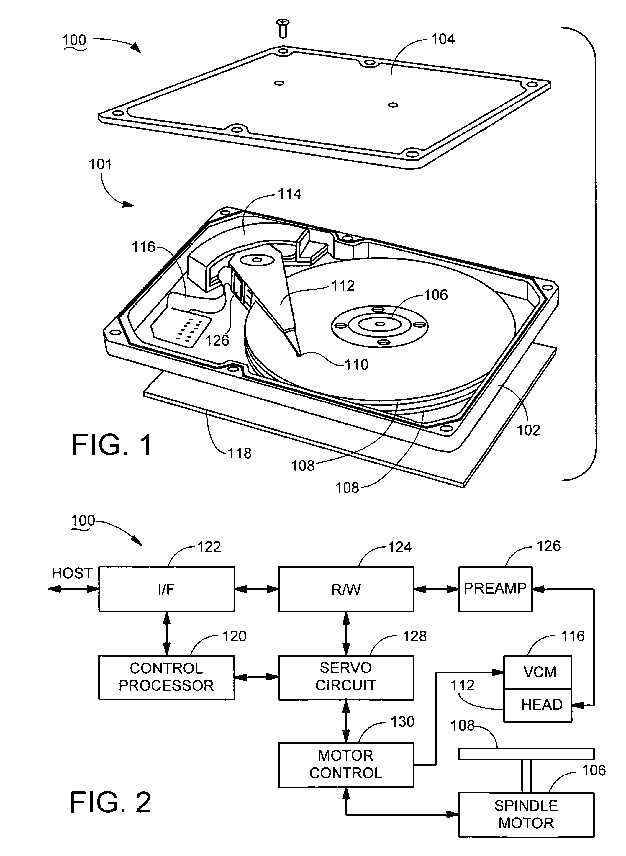
[0027]While the claimed invention has utility in any number of different applications, FIG. 1 has been provided to illustrate a particularly suitable environment in which the claimed invention can be advantageously practiced.

[0028]FIG. 1 shows an exploded, perspective top plan representation of a data storage device 100 of the type used to magnetically store and retrieve computerized user data. The device 100 includes a sealable housing 101 formed from a base deck 102 and a top cover 104.

[0029]The housing 101 provides a controlled interior environment for various constituent components of the device 100, including a brushless direct current (dc) motor 106. The motor 106, also referred to herein as a spindle motor, is used to rotate a number of data storage media 108. The motor 106 is preferably characterized as a three phase, three-input y-connected motor which rotates the media 108 at a constant angular velocity (CAV) during device operation, although such is not limiting.

[0030]The...


PUM


Abstract

Method and apparatus for controlling a brushless dc motor, such as the type used in a data storage device to rotate data storage media. A sequence of drive pulses is applied to rotate the motor. The sequence is switched from first to second motor commutation states at a time determined in relation to changes in elapsed time between successive pulses in the sequence. Each drive pulse has a duration established in relation to an inductance of the motor, and is separated from adjacent pulses by an intermediate delay of predetermined value. A peak elapsed time interval between successive pulses is identified, and the next commutation state is switched in at a selected time after the peak time interval. The sequence preferably accelerates the motor from rest to an intermediate velocity, after which back electromotive force (bemf) commutation is used to accelerate the motor to a final operational velocity.

Description

FIELD OF THE INVENTION[0001]The claimed invention relates generally to the field of electrical motors and more particularly, but not by way of limitation, to an apparatus and method for accelerating a brushless direct current (dc) motor from rest to an intermediate velocity.BACKGROUND[0002]Brushless direct current (dc) motors are used in a variety of applications, such as to rotate a data storage medium in a data storage device. Brushless dc motors, also referred to as spindle motors, include one or more phase windings and a corresponding array of permanent magnets. Current is selectively applied to the phase windings to establish magnetic fields which interact with the magnets to induce rotation of the motor.[0003]A series of commutation states are defined for different mechanical alignments of the phase windings and the magnets. The motor is commutated by selectively switching the particular phase windings to which current is sourced and from which current is sunk as the motor rot...

Claims


Application Information

Patent Timeline
Patent Type & Authority Patents(United States)
IPC IPC(8): H02P6/00
CPCG11B19/28H02P6/182H02P6/205H02P6/22H02P6/21
Inventor HEYDT, JEFFREY A.DULANEY, JR., JAMES W.STREET, DAVID R.SWEZEY, NICHOLASFRANCIS, STUART KEVIN
Owner SEAGATE TECH LLC
Why Eureka
Try Eureka