Equipment bay cable management system

a cable management system and equipment bay technology, applied in the field of equipment and accessories, can solve the problems of inability to provide multifunctional, fully configurable small footprint arrangements, and limitations of conventional fiber management systems in the placement of various parts of the system,

Inactive Publication Date: 2008-10-14
TELLABS OPERATIONS
View PDF7 Cites 65 Cited by
  • Summary
  • Abstract
  • Description
  • Claims
  • Application Information

AI Technical Summary

Problems solved by technology

However, conventional fiber management systems experienced certain disadvantages.
Further, conventional systems are limited in where the various parts of the system may be positioned, such as where to place slack management spools, patch panels, dispersion elements and the like.
Also, conventional fiber management systems are unable to provide multifunctional, fully configurable small footprint arrangements, and offer a limited number of different rack level products that may be utilized with the system.

Method used


Image

  • Equipment bay cable management system
  • Equipment bay cable management system
  • Equipment bay cable management system

Examples


Embodiment Construction

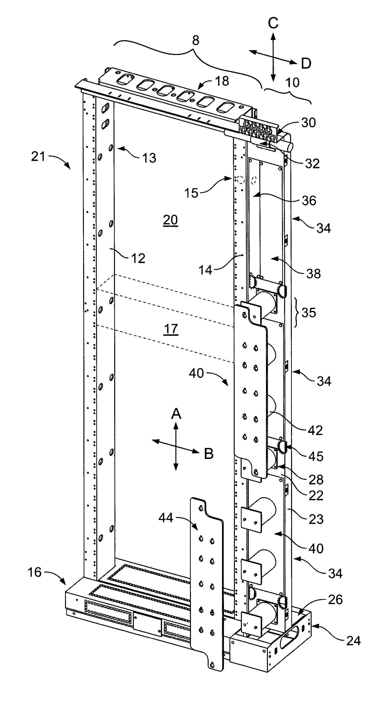
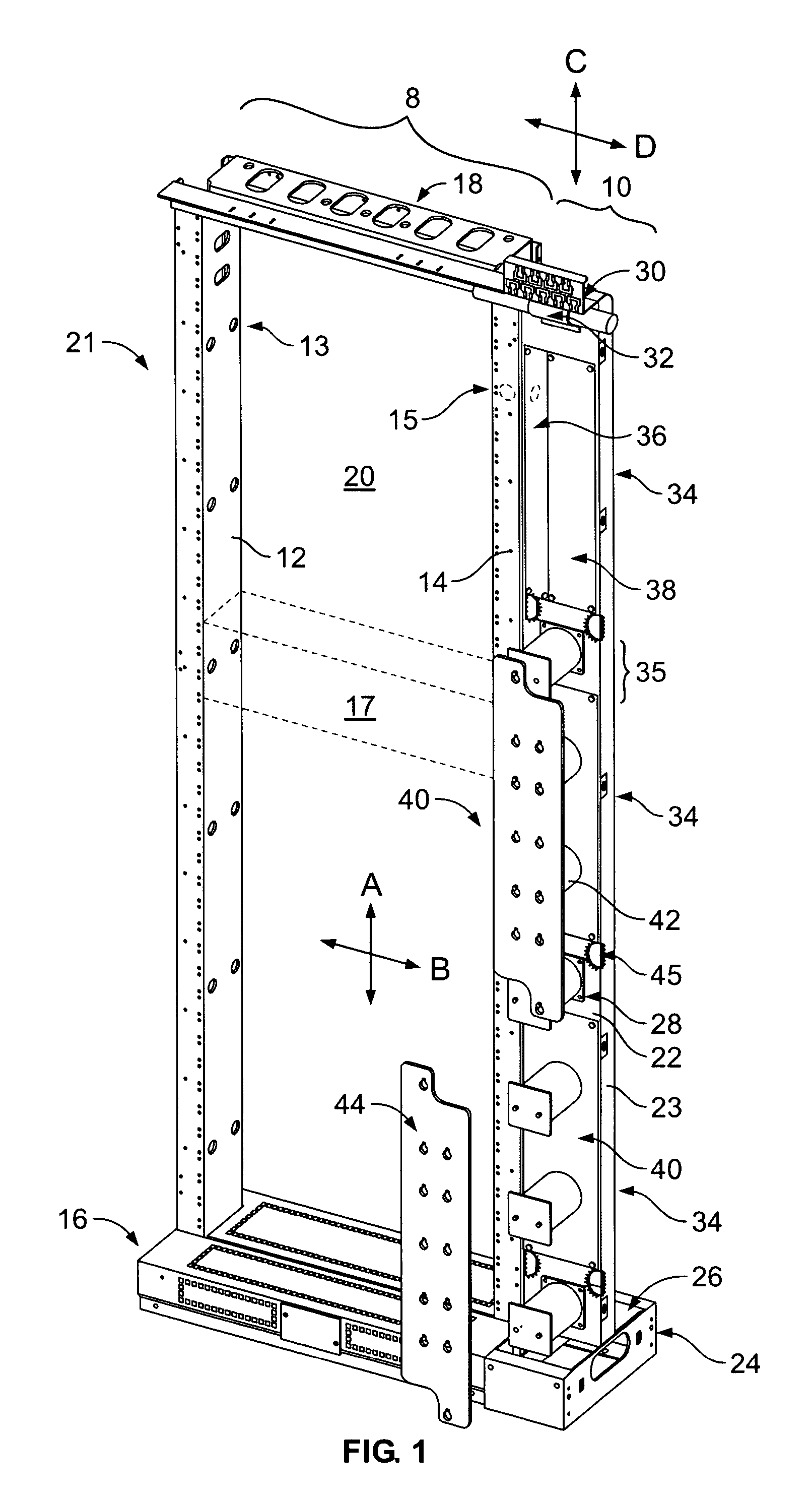
[0014]FIG. 1 illustrates an equipment rack 8 joined to a cable management system 10 that is formed in accordance with an embodiment of the present invention. The equipment rack 8 may be located in a common area with multiple equipment racks of similar construction positioned adjacent one another and spaced apart by a short distance (e.g., a few inches or a few feet).

[0015]Each equipment rack 8 includes a pair of vertical brackets 12, 14 joined at lower ends to a base 16 and at upper ends to an upper crossbeam 18. The brackets 12,14, base 16 and crossbeam 18 are arranged in, and collectively define, an equipment bay receiving plane (generally denoted by crossing vertical and horizontal axes A & B, respectively). The equipment rack 8 includes a front face 21, and the brackets 12, 14 are separated by an equipment bay receiving area 20. The brackets 12,14 each include equipment securing apertures 13, 15, respectively, located immediately across the bay 20 from one another. The apertures...


PUM


Abstract

A cable management system is provided that is configured to be located between adjacent equipment racks, while being vertically oriented to extend upward along a narrow space between the adjacent equipment racks. The cable management system comprises a main panel extending along a vertical longitudinal axis, the main panel having a series of module cutouts provided therein and oriented to extend along the longitudinal axis. The system further includes inter-bay functional modules secured in at least two of the module cutouts. The inter-bay functional modules include at least two of a fiber spool module, a patch panel module and a dispersion compensation module. The main panel includes a front wall having the module cutouts formed therein. The front wall is integrally joined with side flanges extending rearward therefrom to form a channel cross-section.

Description

BACKGROUND OF THE INVENTION[0001]The present invention relates generally to equipment and accessories used with fiber and multiple-fiber cable (e.g., optical fiber, electrical cable and the like). Hereafter, the terms “fiber” and “cable” shall be used inter-changeably. More particularly, the certain embodiments relates to a configurable fiber management assembly that manages fiber connection equipment bays, wherein the manager is capable of storing slack or excess fiber, relieving longitudinal strain on the fiber bundles, and generally facilitating the organization and direction of the fiber to the various equipment of the equipment bay.[0002]Fiber management systems exist today in a variety of configurations. In certain fiber management systems, vertical racks are mounted to the floor and / or ceiling and are configured to support various equipment. Heretofore, fiber management trays have been provided within the fiber management system, with different types of trays being provided f...

Claims


Application Information

Patent Timeline
Patent Type & Authority Patents(United States)
IPC IPC(8): G02B6/00
CPCG02B6/4452
Inventor FARRELL, DANIELPAVLICK, JEROME D.BRINKERHOFF, PHILIP T.
Owner TELLABS OPERATIONS
Why Eureka
Try Eureka