Ophthalmic image sensing apparatus

a technology of image sensing apparatus and ophthalmology, which is applied in the field of ophthalmic image sensing apparatus, can solve the problems of forgetting to return the adjusted light intensity, difficult to set the proper image sensing light intensity from the state of the pupil, and the image of the eye to be examined which is image sensing later becomes dark. , to achieve the effect of reducing the adjustment burden of image sensing light intensity

Inactive Publication Date: 2008-10-21
CANON KK
View PDF7 Cites 21 Cited by
  • Summary
  • Abstract
  • Description
  • Claims
  • Application Information

AI Technical Summary

Benefits of technology

[0014]The present invention aims to provide a fundus image sensing apparatus which reduces an adjustment burden of image sensing light intensity.

Problems solved by technology

However, since being non-mydriasis image sensing cannot disregard the effect of the miosis after image sensing, when right and left eye image sensing is performed continuously, there is a problem that an image of an eye to be examined which is image sensed later becomes dark.
Thereby, there has arisen a trouble that it has been forgotten to return the adjusted light intensity in the case that another person to be examined has taken the place, or the like.
In addition, also as to the adjustment intensity of image sensing light intensity, since a camera person sets it by experience, difference appears in the quality of a sensed image by the presence of experience, or even if he / she is an experienced person, it is said that it is difficult to set proper image sensing light intensity from a state of a pupil which changes with time.
However, even if image sensing is performed in low image sensing light intensity so as to sense images in a state of non-mydriasis, it is not possible to disregard the effect of miosis after image sensing.

Method used


Image

  • Ophthalmic image sensing apparatus
  • Ophthalmic image sensing apparatus
  • Ophthalmic image sensing apparatus

Examples


embodiment 1

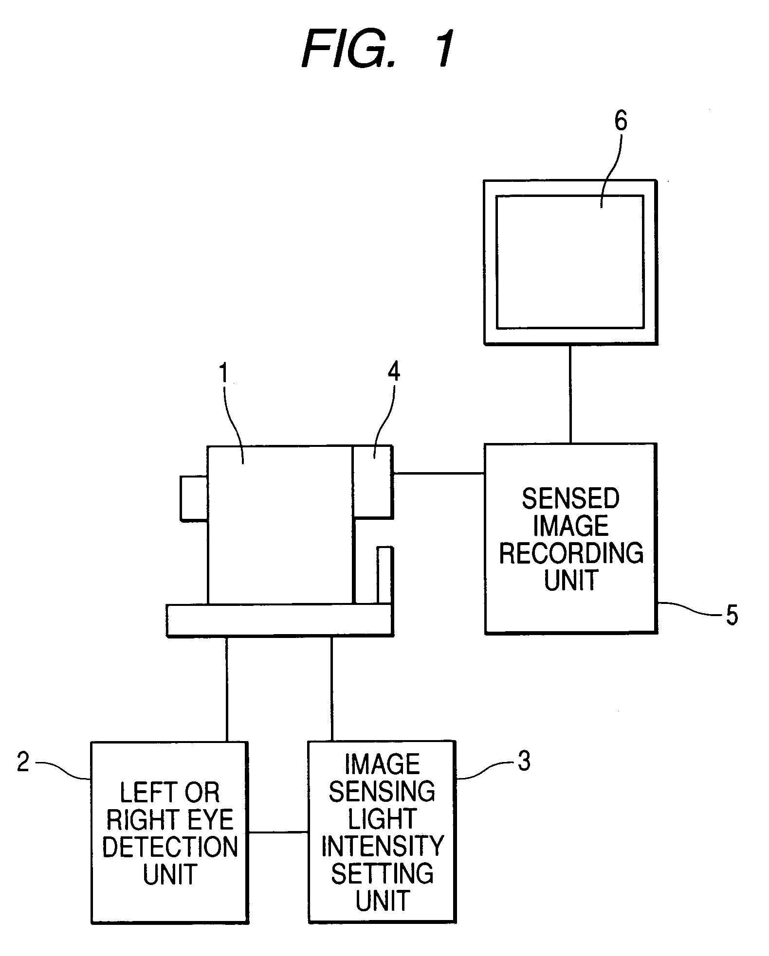
[0047]FIG. 1 shows a structural diagram of an apparatus of a first embodiment. A left or right eye detection unit 2, an image sensing light intensity setting unit 3, and a CCD camera 4 sensing an image of a fundus of eye to be examined are added to a fundus camera 1. An output of the CCD camera 4 is connected to a sensed image recording unit 5, which records a sensed fundus image, and a monitor 6 which displays a sensed image.

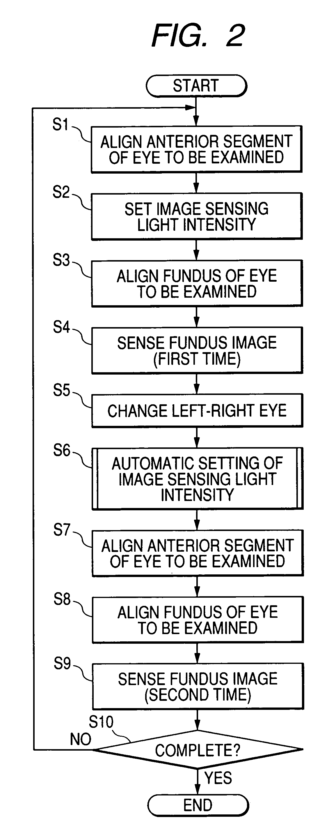
[0048]FIG. 2 is a flowchart of an execution procedure of the first embodiment. In a case of right and left eye fundus image sensing in a mass health examination, the alignment of an anterior segment of eye to be examined is performed first (step S1). This alignment of an eye to be examined is performed by illuminating an anterior segment of eye to be examined by an observing light source for an anterior segment of eye at a near-infrared wavelength in the fundus camera 1, and moving an optical base unit in the fundus camera 1 with observing an image of the anter...

embodiment 2

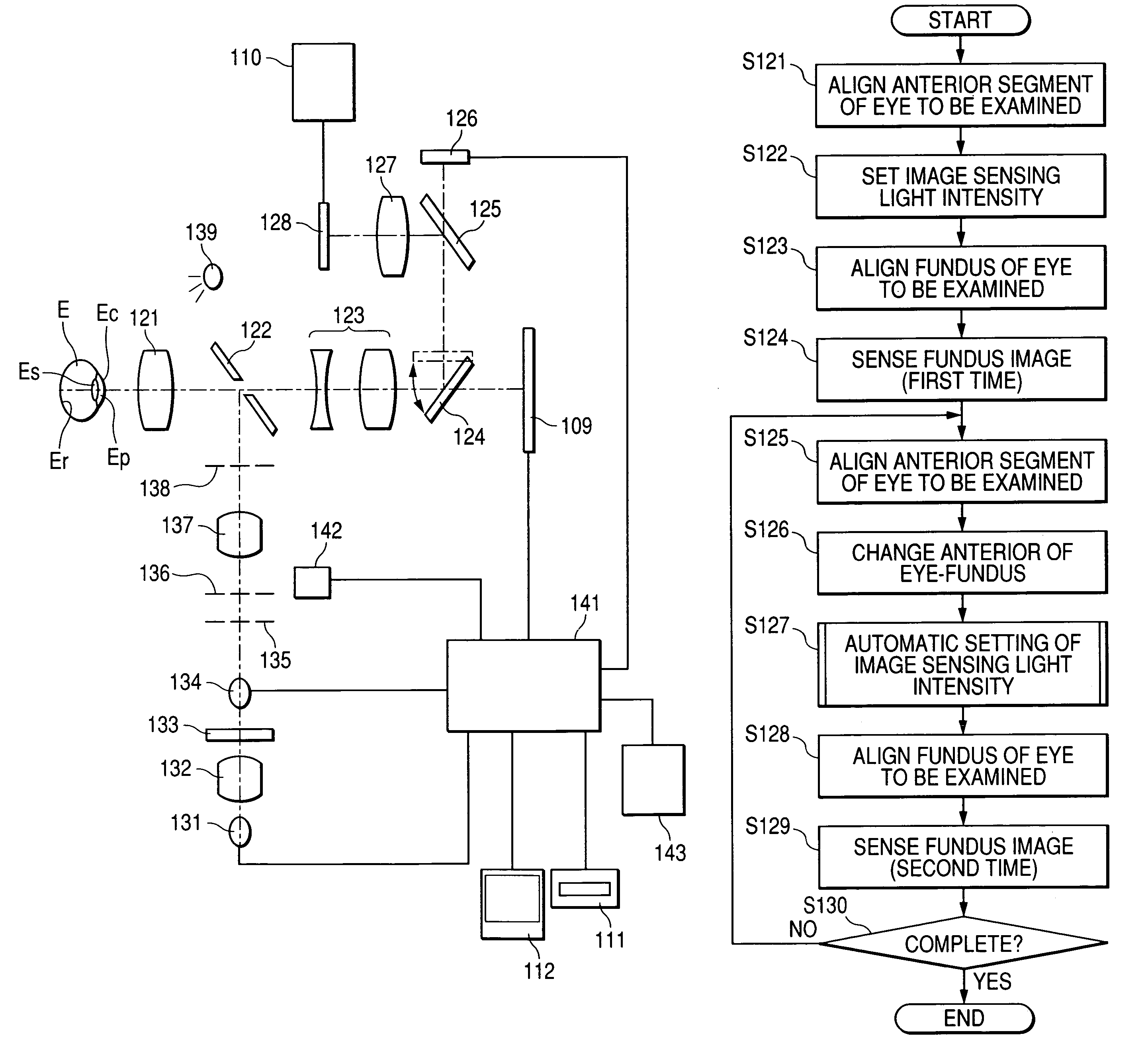
[0072]Although the case that images of right and left eyes are sensed continuously is mentioned as an example in the first embodiment, FIG. 6 is an operation flow chart of a second embodiment in the case of sensing images of the same eye to be examined continuously. Also in this second embodiment, the alignment of an anterior segment of eye (step S21), setting of image sensing light intensity (step S22), alignment of a fundus of eye (step S23), and fundus image sensing (step S24) are executed similarly to the case of the first embodiment.

[0073]At the second image sensing, after performing the alignment of an anterior segment of eye (step S25) first, next image sensing light intensity is set (step S27) with interlocking with the changing operation of the anterior / fundus examination changing switch (step S26) similarly to the first embodiment. A method of setting the image sensing light intensity here conforms to the method described in the first embodiment.

[0074]After the setting of ...

embodiment 3

[0077]FIG. 7 is an operation flow chart in the case of setting the above-mentioned image sensing light intensity automatically within the limits of a predetermined image count in a third embodiment. In a mass health examination and a complete physical examination, there is a case of performing various types of image sensing for the same eye to be examined, such as wide angle image sensing, and narrow angle image sensing with optically enlarging a characteristic region. In this case, since a number of images every eye to be examined is generally the same, the number of images of the same eye to be examined is beforehand registered into the image sensing light intensity setting unit 3 by a number of images setting unit, which is not shown (Step S31).

[0078]When sensing images, the first setting of image sensing light intensity is performed (step S32) similarly to the above-mentioned other embodiments. After the setting of image sensing light intensity is completed and the alignment of ...


PUM


Abstract

In a case of right and left eye fundus image sensing in a mass health examination, the alignment of an anterior segment of an eye to be examined is performed first (S101). When the alignment of the anterior segment of eye is completed, image sensing light intensity is set (S102). The alignment of a fundus segment of the eye to be examined is performed (S103). Furthermore, an image of the fundus of the eye to be examined is sensed by a sensing switch being pushed after the completion of focus adjustment (S104). Next, an optical base unit is moved so that the image sensing of another eye can be performed (S105). A left or right eye detection unit detects that an eye for image sensing is changed with the move of the optical base unit. When the eye for image sensing is changed, an image sensing light intensity setting unit sets image sensing light intensity by adding a predetermined amount, or changing the sets image sensing light intensity according to a diameter of a pupil (S106). Then, alignment and the like are performed similarly to S101 and S103 (S107, S108), and an image of another eye is sensed.

Description

BACKGROUND OF THE INVENTION[0001]1. Field of the Invention[0002]The present invention relates to an ophthalmic image sensing apparatus such as a fundus camera used in fundus examinations such as a mass health examination.[0003]2. Related Background Art[0004]As disclosed in Japanese Patent Application Laid-Open No. H10-75932 official gazette and Japanese Patent Application Laid-Open No. H10-113336, in mass health examinations such as a resident medical examination and a company medical examination, fundus examinations are implemented respectively. Although fundus image sensing of only one eye was performed before, since a finding may have appeared in the other eye which has not been examined, right and left eye image sensing has implemented in recent years.[0005]In fundus image sensing in a mass health examination, non-mydriasis image sensing which does not need a mydriatic is performed usually. The non-mydriasis image sensing is performed after urging the natural mydriasis of an eye...

Claims


Application Information

Patent Timeline
Patent Type & Authority Patents(United States)
IPC IPC(8): A61B3/14
CPCA61B3/12A61B3/15
Inventor KASHIWAGI, KENICHISEKIGUCHI, KYOJI
Owner CANON KK
Why Eureka
Try Eureka