
Locking mechanism for a theft-resistant mailbox

a locking mechanism and mailbox technology, applied in the field of locking mechanisms, can solve the problems of increasing theft and general concerns of personal security, putting valuable correspondence at risk, and mail delivered by postal carriers is often left unguarded for hours or even days at a tim

Active Publication Date: 2008-10-28
BOLLES DAVID J
View PDF16 Cites 14 Cited by
  • Summary
  • Abstract
  • Description
  • Claims
  • Application Information

AI Technical Summary

Problems solved by technology

Recently, an increase in theft and overall concerns of personal security have drawn into question the wisdom of relying on non-locking mailboxes for curbside mail delivery.
Mail delivered by a postal carrier is often left unguarded for hours or even days at a time.
Valuable correspondence, such as bank statements, negotiable instruments, and credit cards, are placed at risk of being stolen, particularly in light of a rising trend in identity theft.
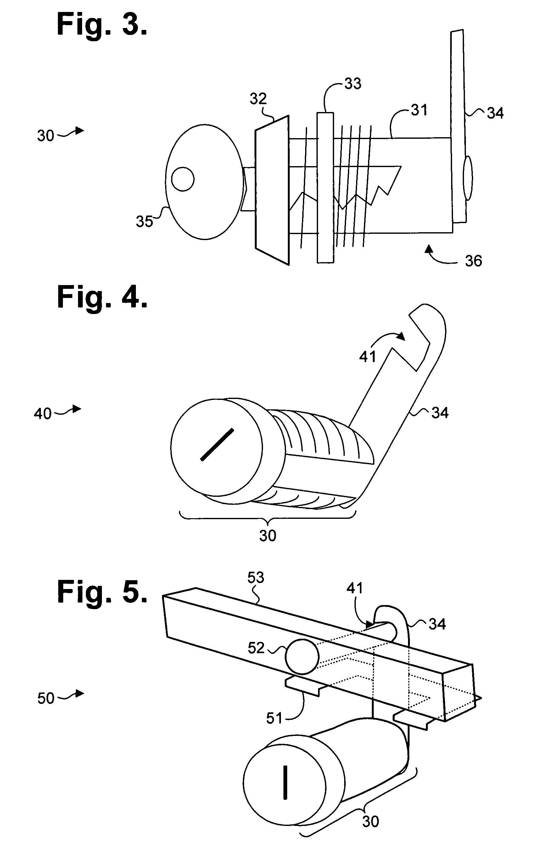
However, the locked mailbox door can be compromised by forcibly prying the mailbox door using a lever, such as a screwdriver, to deform the internal cam and bend the mailbox door open, thereby gaining access to the contents stored within.

Method used


Image

  • Locking mechanism for a theft-resistant mailbox
  • Locking mechanism for a theft-resistant mailbox
  • Locking mechanism for a theft-resistant mailbox

Examples


Embodiment Construction

Theft-Resistant Mailbox with Conventional Mounting Bracket

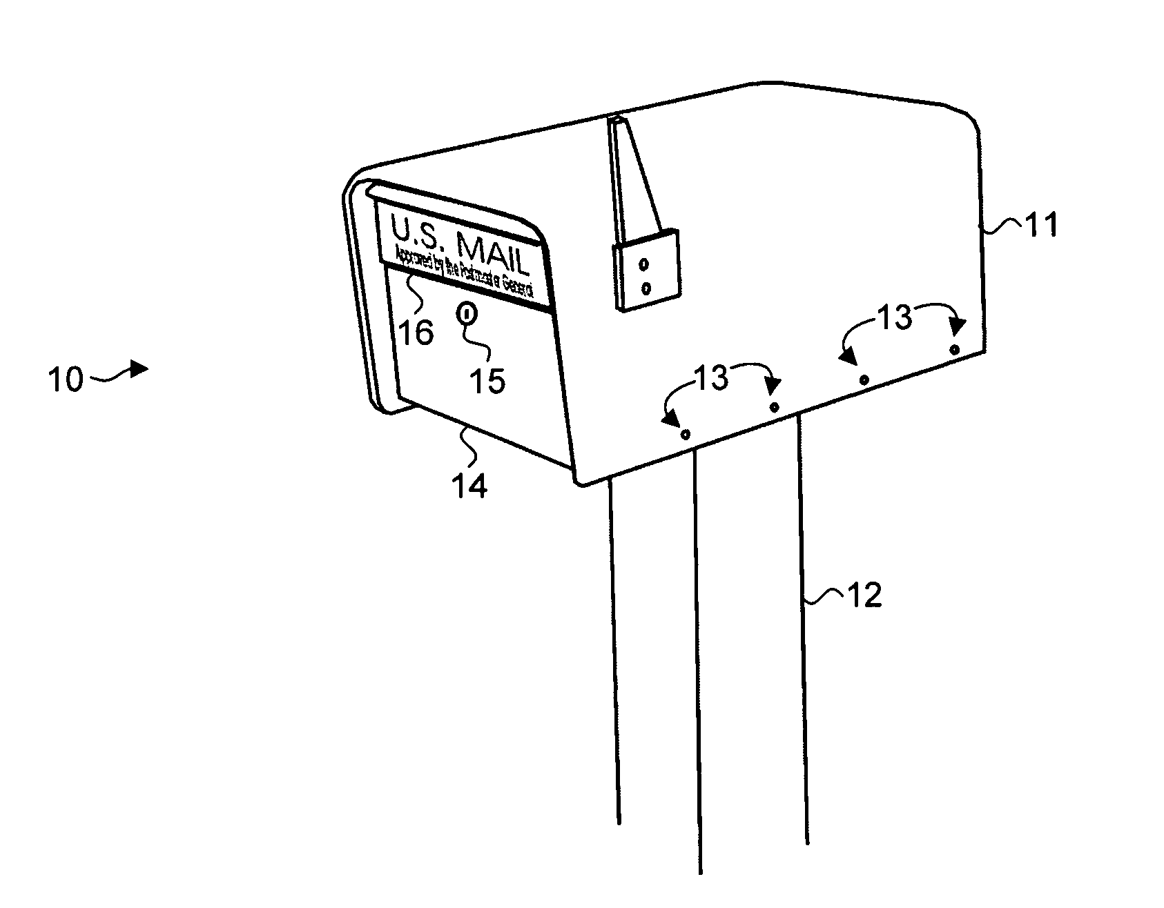
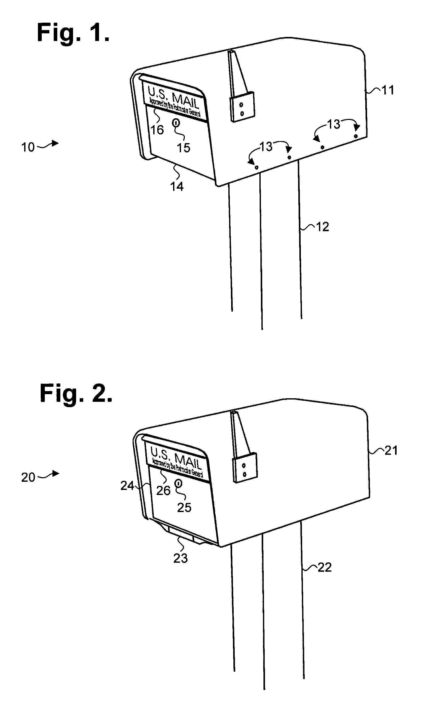
[0017]Conventionally, mailboxes are frequently installed on a mounting post or other level surface to permit easy curbside access by postal delivery vehicles and mail carriers. FIG. 1 is a perspective view showing, by way of example, a theft-resistant mailbox 10 with conventional mounting bracket, in accordance with one embodiment. The mailbox 10 includes a housing 111 that is roughly rectangular in shape, but which is open on the bottom and front surfaces. The front surface generally means the side of the mailbox 10 by which mail is received through one or more doors. The housing 11 is installed on a mounting post or other level surface 12 using a conventional mounting bracket (not shown). The housing is fixedly attached to the mounting bracket with housing fasteners 13, which are generally exposed around the outer bottom margin or other outside surface of the housing 11.

[0018]The mailbox 10 also includes a lockable mail del...


PUM


Abstract

A locking mechanism for a theft resistant mailbox includes a door assembly. A door is affixed to a frame by at least one pivot point. A cam includes a lever rotatably engaged to a fixed surface at a mounting point and defines a cutout oriented to be removably engaged to a striker attached to a separate surface abutting the fixed surface to form a lock for the door upon urging of the cam along an angle of rotation defined about the mounting point. An anti-pry plate is attached to the fixed surface and juxtapositioned about the cam throughout the angle of rotation by which the lock is effected. The fixed surface includes one of the frame and the door. The separate surface includes an other one of the frame and the door. The fixed surface and the separate surface are provided independent of the at least one pivot point.

Description

CROSS-REFERENCE TO RELATED APPLICATION[0001]This non-provisional patent application claims priority under 35 U.S.C. § 119(e) to commonly-owned U.S. provisional patent application Ser. No. 60 / 808,469, filed May 24, 2006, the disclosure of which is incorporated by reference.FIELD OF THE INVENTION[0002]The invention relates in general to locking mechanisms and, in particular, to a locking mechanism for a theft-resistant mailbox.BACKGROUND OF THE INVENTION[0003]Recently, an increase in theft and overall concerns of personal security have drawn into question the wisdom of relying on non-locking mailboxes for curbside mail delivery. Mail delivered by a postal carrier is often left unguarded for hours or even days at a time. Valuable correspondence, such as bank statements, negotiable instruments, and credit cards, are placed at risk of being stolen, particularly in light of a rising trend in identity theft.[0004]Providing a locking mechanism on mailboxes provides a partial solution. A loc...

Claims


Application Information

Patent Timeline
Patent Type & Authority Patents(United States)
IPC IPC(8): B65G11/04
CPCA47G29/1209E05B17/2088E05B63/12E05B77/44E05C3/042E05B83/30E05B65/44Y10T70/5549Y10T70/7921
Inventor BOLLES, DAVID J.
Owner BOLLES DAVID J
Learn More