Self testing ground fault circuit interrupter (GFCI)

a fault circuit interrupter and self-testing technology, applied in the direction of frequency to phase shift conversion, emergency protective arrangements for limiting excess voltage/current, instruments, etc., can solve the problems of increasing interruptions, medical equipment cannot tolerate interruptions of a prolonged duration, and all power being removed from the load, so as to determine the operability of the switching device

Active Publication Date: 2008-10-28
HUBBELL INC
View PDF19 Cites 63 Cited by
  • Summary
  • Abstract
  • Description
  • Claims
  • Application Information

AI Technical Summary

Benefits of technology

[0015]In another embodiment of the present invention, the controller turns on a switching device to determine if a current flows in the switching device and determines the operability of the switching device by detecting a discharge of a capacitor when the switching device is on.
[0016]In still another embodiment of the present invention, the controller determines the operability of the solenoid by detecting a discharge of the capacitor during a negative half cycle of a sinusoidal input.

Problems solved by technology

The fault condition can result when a person comes into contact with the hot side of the AC load and an earth ground, a situation which can result in serious injury.
When such an imbalance is detected, a relay or circuit breaker within the GFCI device is immediately tripped to an open condition, thereby removing all power from the load.
The latter type of connection, which may result from a defective load or from improper wiring, is potentially dangerous because it can prevent a conventional GFCI device from tripping at the required threshold level of differential current when a line-to-ground fault occurs.
This can create a problem when sensitive equipment such as medical equipment is connected to the GFCI.
The medical equipment cannot tolerate interruptions of a prolonged duration.
However, frequent testing often compounds the problem by increasing interruptions to sensitive equipment that is connected to the GFCI.
However, users usually forget or simply choose to ignore performing the manual tests.
An additional problem is that if the GFCI has a high cost, end users may select a lower cost GFCI that has the above mentioned problems without fully being aware of the disadvantages of the GFCI.

Method used


Image

  • Self testing ground fault circuit interrupter (GFCI)
  • Self testing ground fault circuit interrupter (GFCI)
  • Self testing ground fault circuit interrupter (GFCI)

Examples


Embodiment Construction

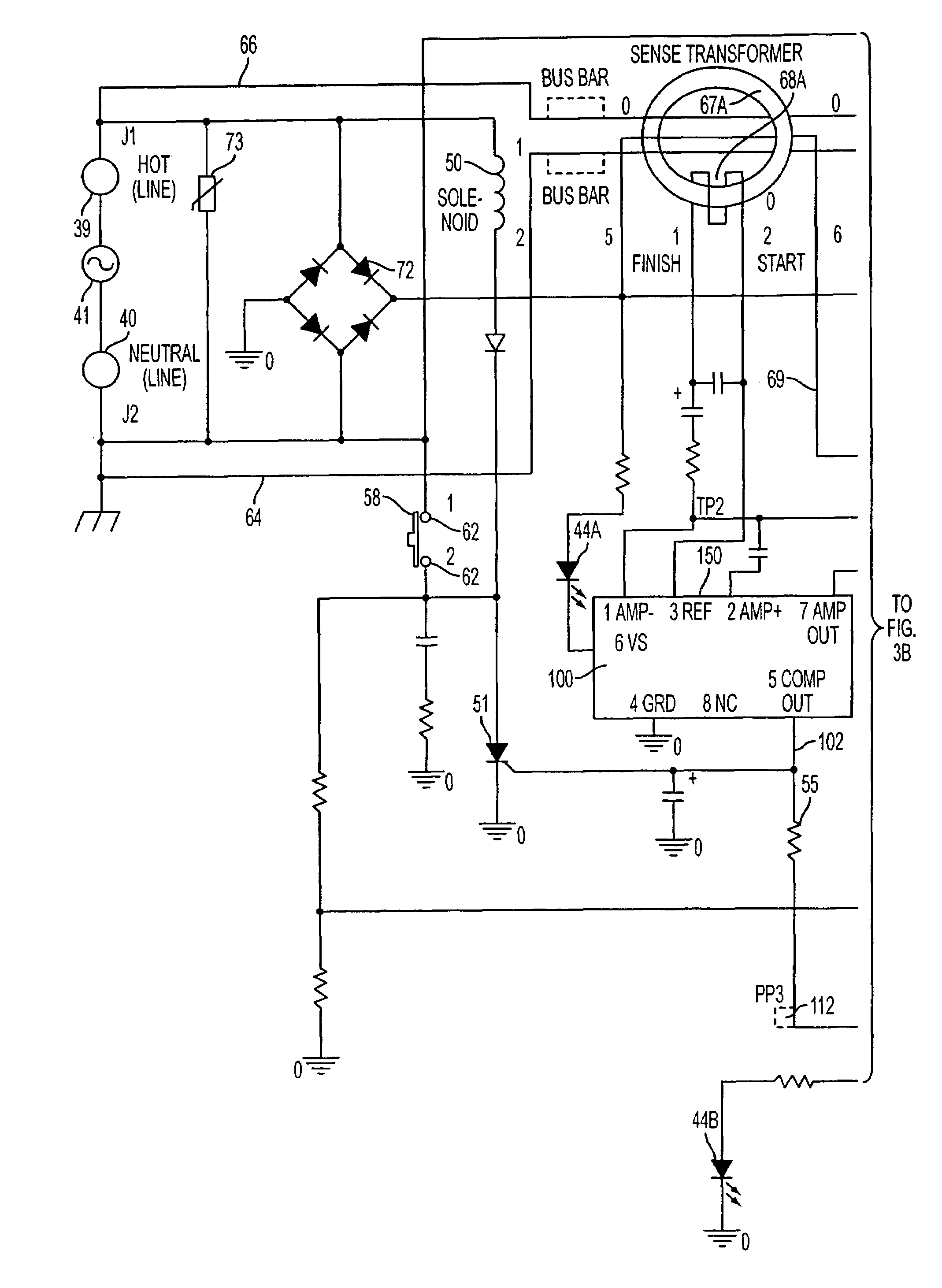
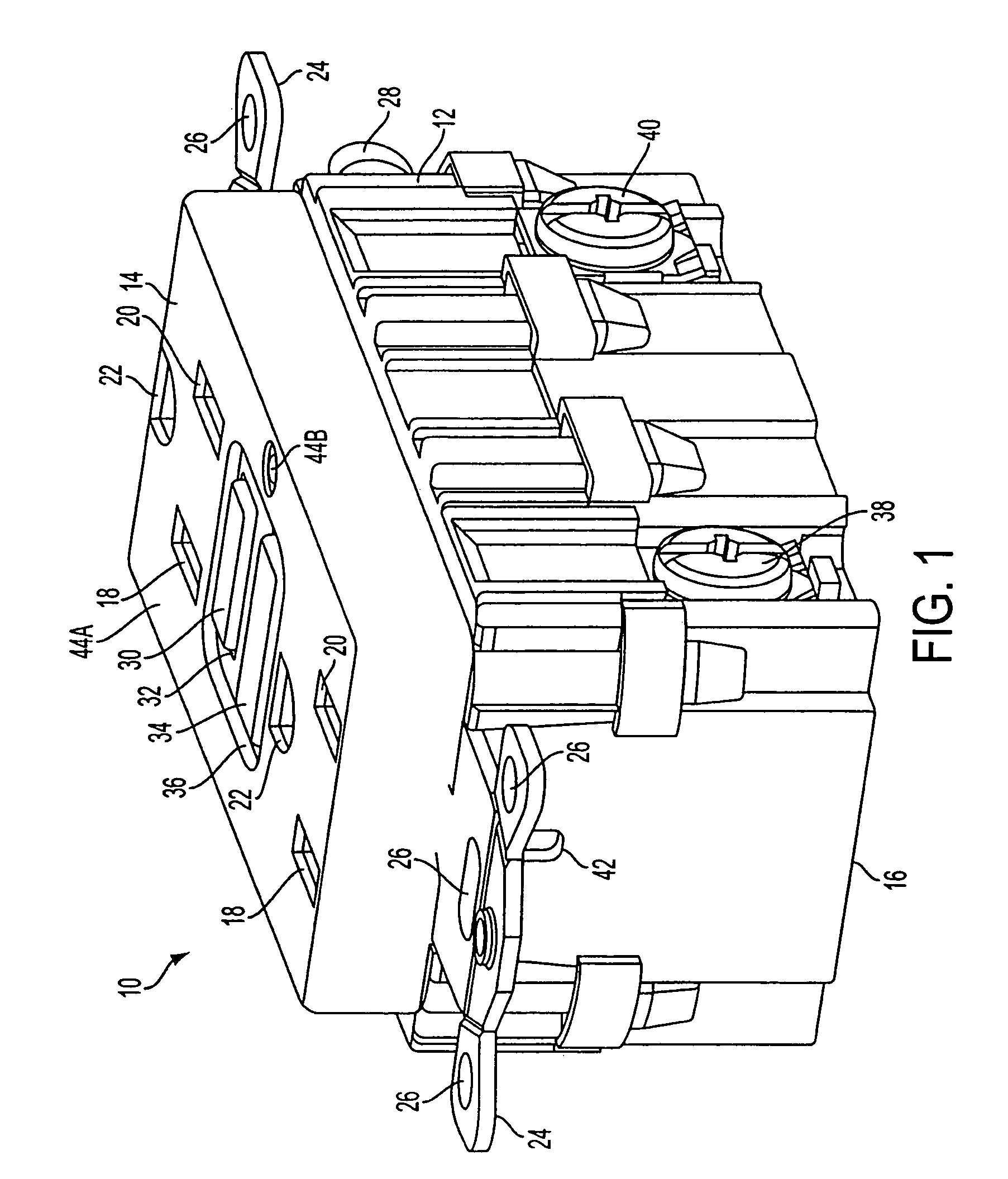
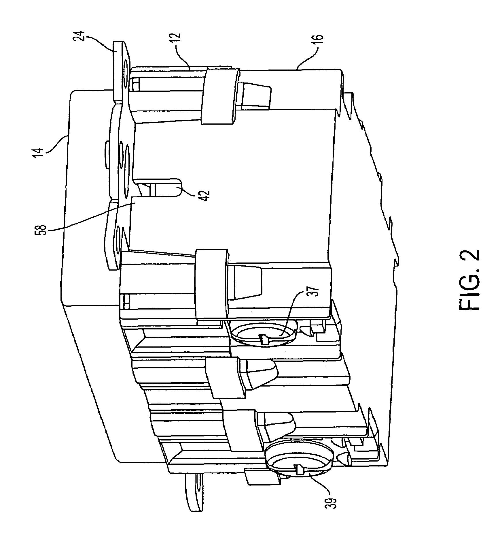
[0028]FIG. 1 is a perspective view of an example of a ground fault circuit interrupting (GFCI) device 10 in accordance with an embodiment of the present invention. The GFCI device 10 comprises a housing 12 having a cover portion 14 and a rear portion 16. The GFCI also includes an inner housing 13 (See FIG. 4) when the cover portion 14 is removed from the rear portion 16. The cover portion 14 and rear portion are removably secured to each other via fastening means such as clips, screws, brackets, tabs and the like. The cover portion includes plugin slots (also known as face receptacles) 18 and 20 and grounding slots 22. It should be appreciated by those skilled in the art that plugin slots 18 and 20 and grounding slots 22 can accommodate polarized, non-polarized, grounded or non-grounded blades of a male plug. The male plug can be a two wire or three wire plug without departing from the scope of the embodiment of the present invention.

[0029]The GFCI receptacle 10 further includes mou...


PUM


Abstract

A self testing fault detector having a line side and a load side and a conductive path there between, said apparatus is provided. The self testing fault detector includes a controller, adapted to perform periodic status tests on a protection circuit of the self testing fault detector without interrupting power to the load.

Description

CROSS-REFERENCE TO RELATED APPLICATIONS[0001]Related subject matter is disclosed in U.S. Pat. No. 7,184,250, filed on, May 9, 2003, and assigned Ser. No. 10 / 434,101, entitled “GFCI THAT CANNOT BE RESET UNTIL WIRED CORRECTLY ON LINE SIDE AND POWER IS APPLIED,” the entire contents of said application being incorporated herein by reference.BACKGROUND OF THE INVENTION[0002]1. Field of the Invention[0003]The present invention relates generally to a self testing fault interrupting device, such as a ground fault circuit interrupter (GFCI). More particularly, the present invention relates to a self testing fault interrupting device where a periodic self test is performed on the fault detection and tripping portions of the device independent of a manual test.[0004]2. Background of the Invention[0005]Fault interrupting devices are designed to trip in response to the detection of a fault condition at an AC load. The fault condition can result when a person comes into contact with the hot side ...

Claims


Application Information

Patent Timeline
Patent Type & Authority Patents(United States)
IPC IPC(8): G08B21/00
CPCH01H83/04H01H9/56H01H2071/044
Inventor BALDWIN, JOHN R.YU, DAVIDBONILLA, NELSON
Owner HUBBELL INC
Why Eureka
Try Eureka