Disk apparatus

a technology of a disk and a rotating disk, which is applied in the direction of record information storage, record carrier contruction details, instruments, etc., can solve the problems of increasing the component count, the disk cannot be made to rotate toward the central portion of the disk, and the possibility of so as to prevent the drop of the disk and reduce the component count. , the effect of small component coun

Inactive Publication Date: 2008-10-28
MITSUBISHI ELECTRIC CORP
View PDF10 Cites 10 Cited by
  • Summary
  • Abstract
  • Description
  • Claims
  • Application Information

AI Technical Summary

Benefits of technology

[0008]The present invention is made in order to solve the above-mentioned problems, and it is therefore an object of the present invention to provide a small, slim, and high-reliability disk apparatus having a small component count, which prevents downward inclination of a disk stored in each stocker so as to prevent drop of the disk and which restricts a vertical position of the disk stored in each stocker.
[0009]In accordance with an aspect of the present invention, there is provided a disk apparatus including: a playback unit having a reading unit for reading information recorded on a disk, and a turntable on which the disk is placed, the playback unit being movable between a lateral side of a disk conveyance path and a central portion of the disk; an arc-shaped stocker for stocking the disk, the stocker being shaped like a part of a circle whose more than half of its area including a center is removed in order to make it possible for the playback unit to move toward the central portion of the disk; and a supporting member disposed separately from the stocker opposite to a part of the disk which is not held by the stocker, the supporting member restricting horizontal movements of the disk. Therefore, the component count can be reduced.
[0010]In accordance with another aspect of the present invention, there is provided a disk apparatus including: a playback unit having a reading unit for reading information recorded on a disk, and a turntable on which the disk is placed, the playback unit being movable between a lateral side of a disk conveyance path and a central portion of the disk; an arc-shaped stocker for stocking the disk, the stocker being shaped like a part of a circle whose more than half of its area including a center is removed in order to make it possible for the playback unit to move toward the central portion of the disk; and a rotatable supporting member having a sandwiching portion that sandwiches a part of the disk which is not held by the stocker, the supporting member restricting a vertical position of the disk. Therefore, the disk apparatus can certainly prevent the disk from inclining downward toward the removed part of the stocker.
[0011]As a result, while the manufacturing cost of the disk apparatus can be reduced, the disk apparatus can certainly hold disks stocked therein with them being placed in horizontal positions. In addition, even if the elevation position at which the playback unit is moved horizontally is made to be close to the elevation position at where a disk is stocked into the stocker in order to slim down the disk apparatus, there is no interference with horizontal movements of the playback unit.

Problems solved by technology

A problem with the related art disk apparatus is that since it supports a part of the perimeter of a disk which is in the removed part of each stocker by using the supporting member disposed on each stocker and brought into contact with the part of the perimeter of the disk so as to prevent a displacement of the disk in a horizontal direction, the component count increases.
However, since the load of the disk stored in each stocker is held only by each stocker, there is a possibility that the disk stored in each stocker may be inclined downward toward the removed part of each stocker and the disk may drop into the disk apparatus and it is impossible to prevent the possibility of the drop of the disk.
Furthermore, when a level at which the playback unit is horizontally moved and a level at which each stocker stores a disk therein are made to be close to each other in order to miniaturize and slim down the disk apparatus, if the disk stored in each stocker is inclined, the playback unit is brought into contact with the edge of the disk and cannot be made to rotate toward the central portion of the disk.

Method used


Image

  • Disk apparatus
  • Disk apparatus
  • Disk apparatus

Examples


embodiment 1

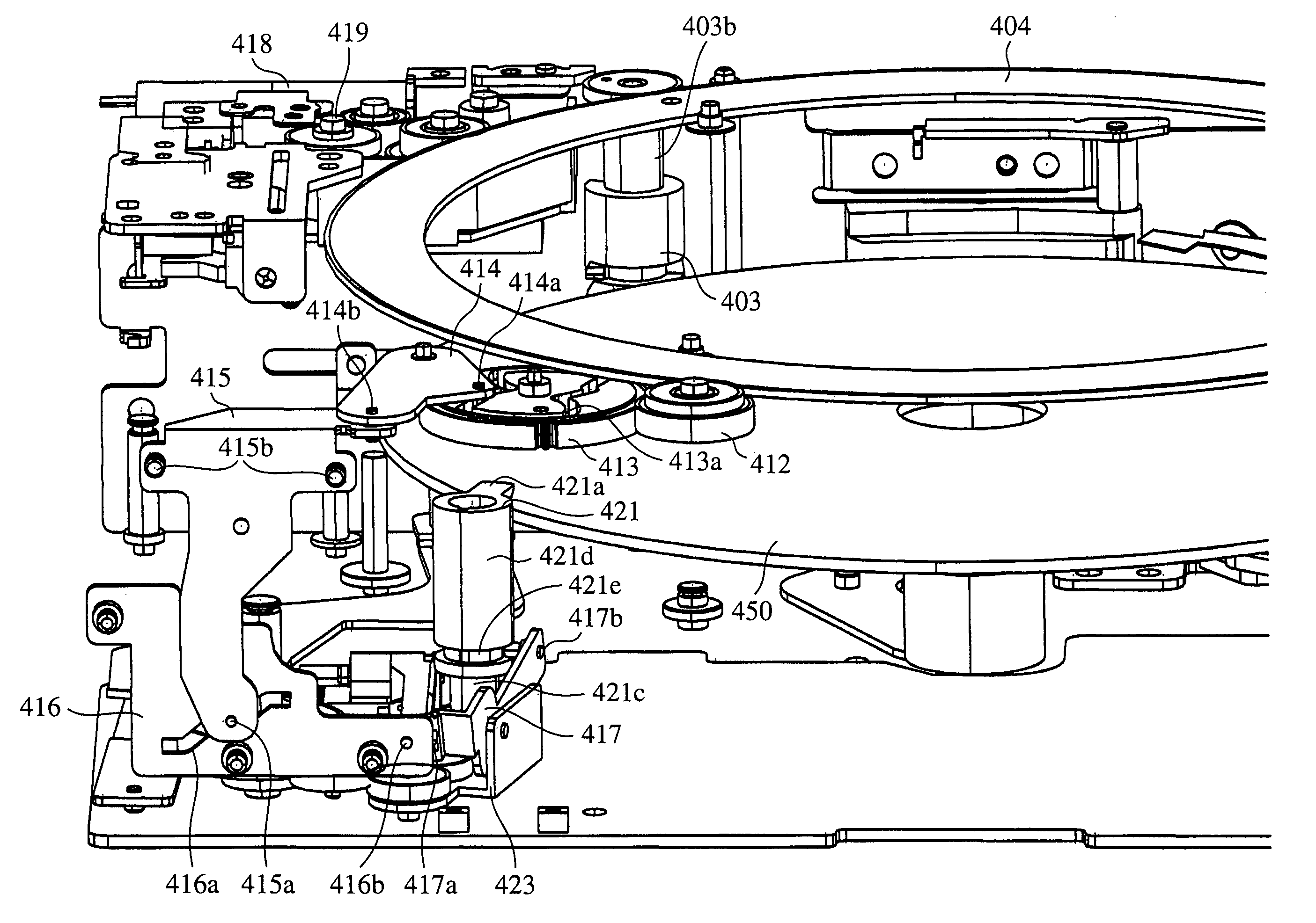
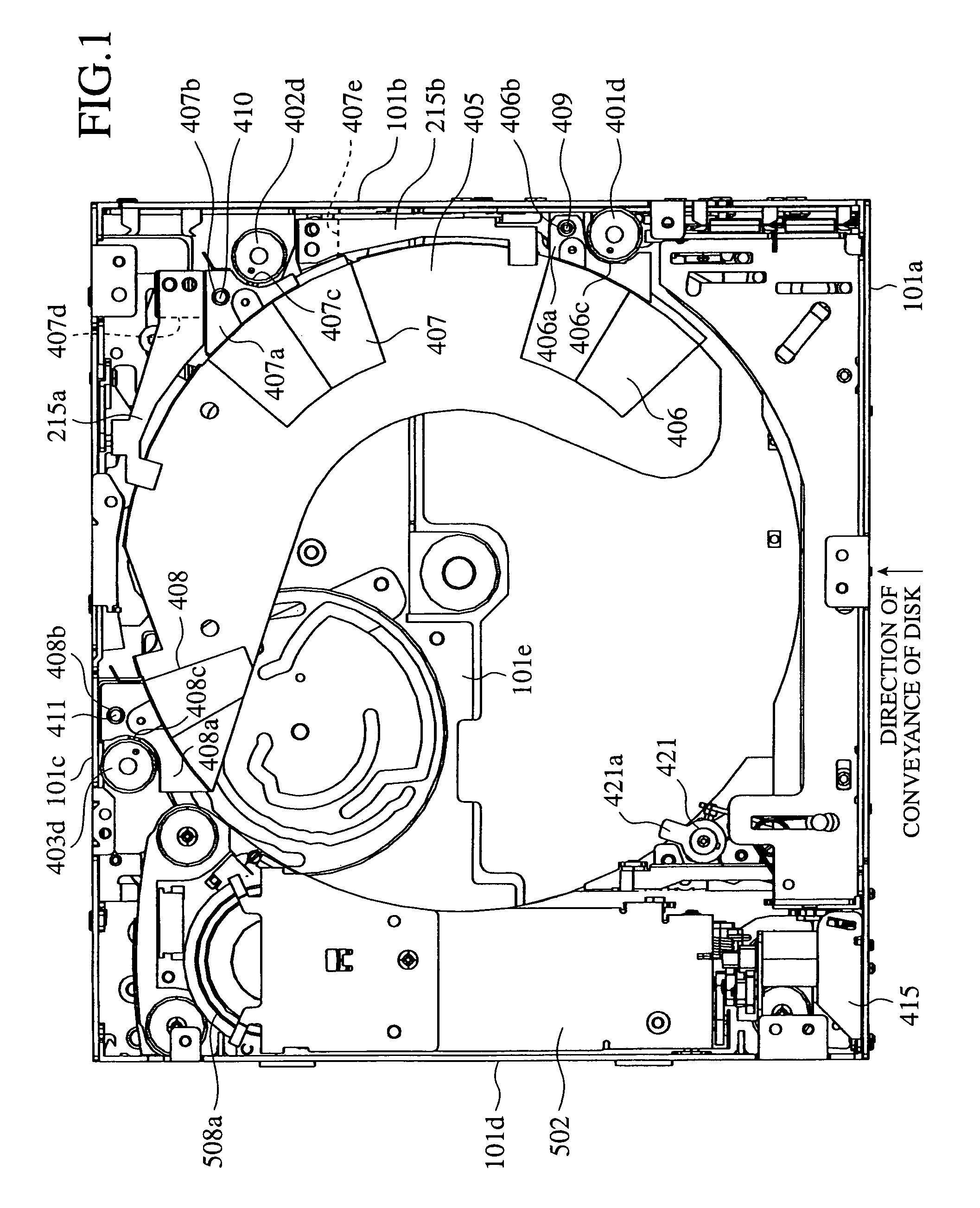
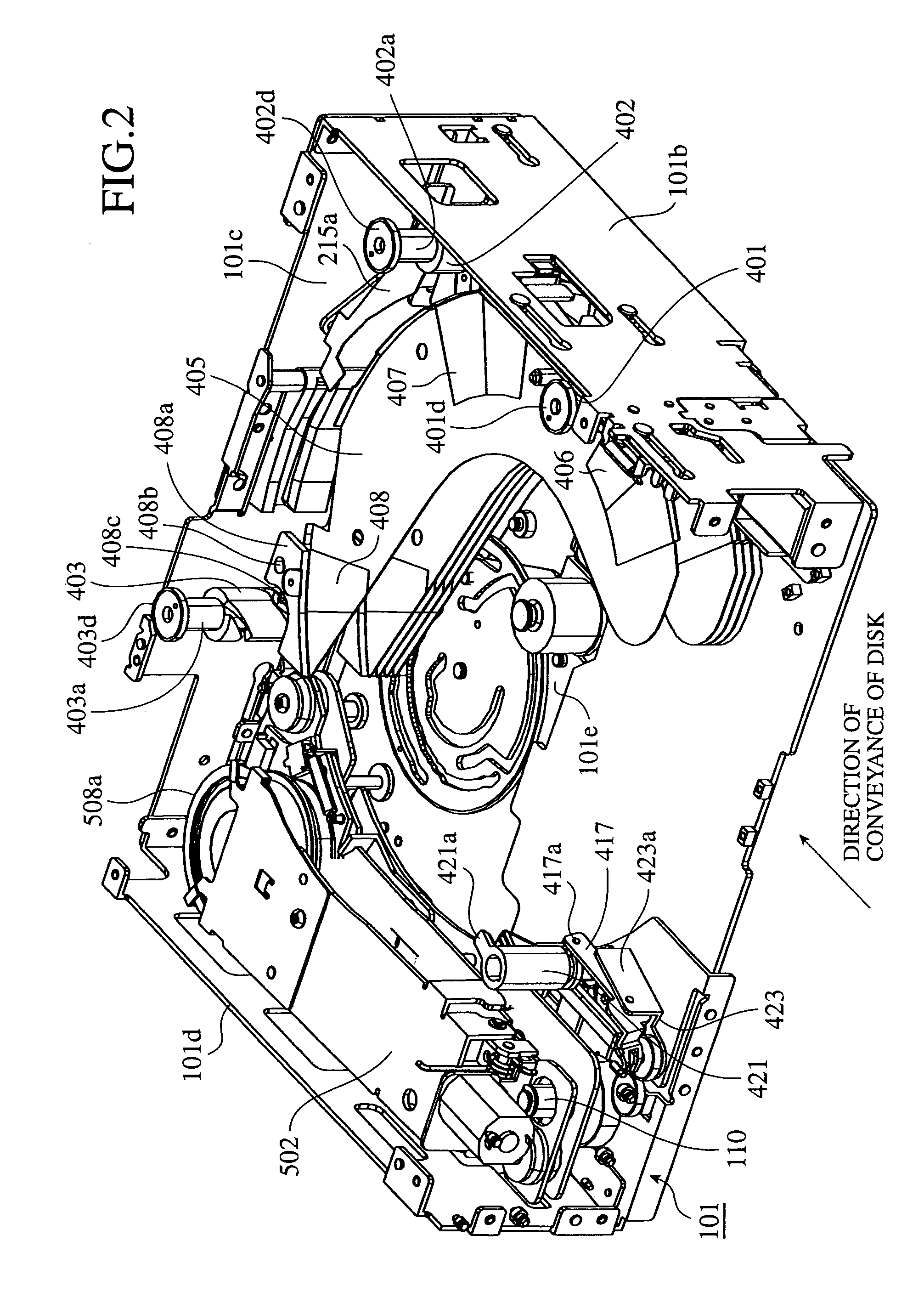
[0048]FIG. 1 is a plan view showing the internal structure of a disk apparatus in accordance with the present invention, FIG. 2 is a perspective diagram showing the internal structure of the disk apparatus, but in which a top plate and a front side plate of a housing are removed, FIG. 3 is a front view showing a left half of a main part of the disk apparatus, but showing a state in which a disk is inserted into the disk apparatus, FIG. 4 is a front view of the left half of the main part of the disk apparatus, but showing a state in which a disk guide member is moved upward, FIG. 5 is a perspective diagram of the disk apparatus, but showing a state in which the disk is raised to a playback unit entry position in the state of FIG. 4, and FIG. 6 is a perspective diagram of the disk apparatus, but showing a state in which the disk is clamped and held on a turntable.

[0049]As shown in those figures, a drive mechanism, a disk insertion / ejection mechanism, a disk changer mechanism, a playba...


PUM

PropertyMeasurementUnit
anglesaaaaaaaaaa
anglesaaaaaaaaaa
anglesaaaaaaaaaa

Abstract

A disk apparatus includes a playback unit having a reading unit for reading information recorded on a disk, and a turntable on which the disk is placed, the playback unit being movable between a lateral side of a disk conveying path and a central portion of the disk, an arc-shaped stocker for stocking the disk, the stocker being shaped like a part of a circle whose more than half of its area including a center is removed in order to make it possible for the playback unit to move toward the central portion of the disk, and a supporting member disposed separately from the stocker opposite to a part of the disk which is not held by the stocker, the supporting member restricting horizontal movements of the disk.

Description

BACKGROUND OF THE INVENTION[0001]1. Field of the Invention[0002]The present invention relates to a disk apparatus that plays back information stored in a disk. More particularly, it relates to a disk apparatus that can be used with being mounted in a moving object, such as a motor vehicle.[0003]2. Description of Related Art[0004]A related art disk apparatus is provided with a playback unit that can move between a lateral side of a disk conveyance path and a central portion of a disk stored therein, and a plurality of stockers each for stocking an inserted disk, each stocker being shaped like a part of a circle whose more than half of its area including a center is removed in order to make it possible for the playback unit to move toward the central portion of a disk stored in each stocker, supports a part of the perimeter of a disk which is in the removed part of each stocker by using a supporting member disposed on each stocker and brought into contact with the part of the perimete...

Claims


Application Information

Patent Timeline
Patent Type & Authority Patents(United States)
IPC IPC(8): G11B17/03G11B17/26G11B7/085G11B17/04G11B17/22G11B21/08
CPCG11B17/021G11B17/223
Inventor ITO, SHIGEHIRO
Owner MITSUBISHI ELECTRIC CORP
Why Eureka
Try Eureka