Circuit for a radio system, use and method for operation

a radio system and circuit technology, applied in the field of circuits for radio systems, can solve the problem that the symbol frequency cannot be obtained through integer division of the output clock signal, and achieve the effect of improving the circuit of the radio system

Active Publication Date: 2012-12-25
ATMEL CORP
View PDF5 Cites 0 Cited by
  • Summary
  • Abstract
  • Description
  • Claims
  • Application Information

AI Technical Summary

Benefits of technology

[0023]A logic element can be designed to change the integer divisor values of the modulo divider, for example by switchover between two divisor values. In this regard, the logic element is designed such that an input frequency at the input of a symbol counter is approximated to a predetermined symbol frequency by the blanking and the changing of the integer divisor values. The symbol counter is designed to provide the system time from a number of counted symbols. The symbol time can thus exhibit a small count error on account of the approximation.

Problems solved by technology

The symbol frequency cannot be obtained through integer division of the output clock signal, however.

Method used


Image

  • Circuit for a radio system, use and method for operation
  • Circuit for a radio system, use and method for operation

Examples


Embodiment Construction

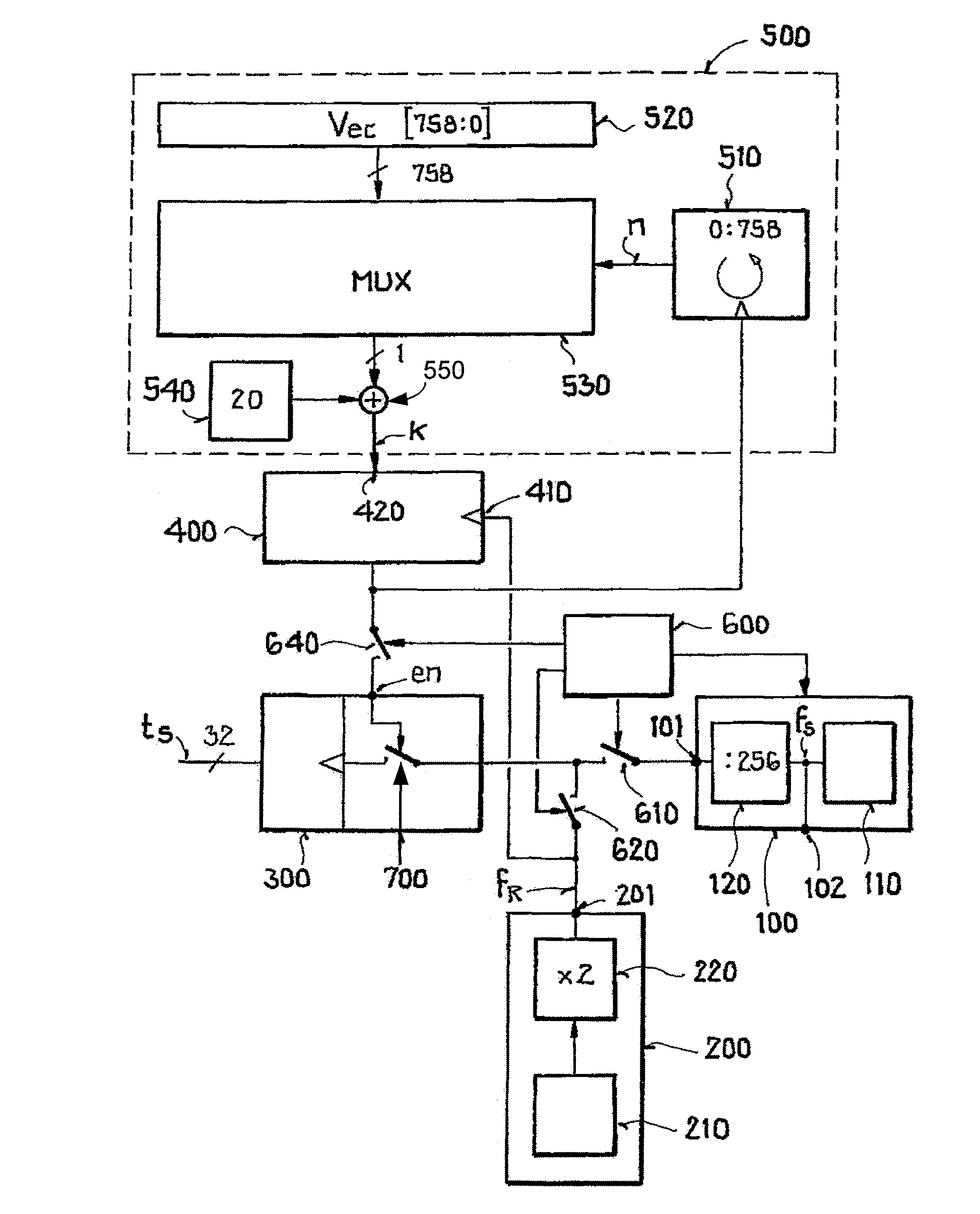
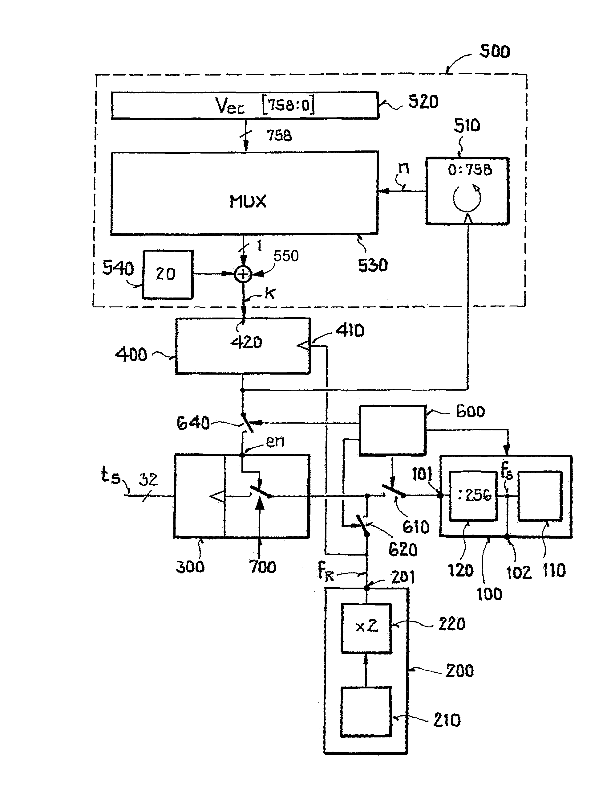
[0035]The symbol period used for the radio system according to the industry standard IEEE 802.15.4 is 16 μs. If the radio system is in an operating mode (active state), the 16 MHz system clock can be used as the time base for a system time. In a sleep mode (inactive state), this system clock generator is switched off, and only a quartz clock crystal (RTC, real-time clock) with a frequency of 32.768 KHz is available. Doubling the frequency to 65.536 KHz results in a period of 15.258 μs, which differs significantly from the desired symbol period of the system time of the radio system.

[0036]The block diagram shown in the FIGURE makes it possible to limit the possible count error to one symbol period independent of the operating time of the symbol counter. Of course, the quartz clock crystal here is not ideal either, and can cause an additional error as a result of frequency deviations. As a result of this error and other error sources, such as the system clock, synchronization in the r...


PUM


Abstract

A circuit and method of operation for a circuit of a radio system in which a system time is divided into symbols, in which a system clock generator is activated in an operating mode, so that the system time is determined from an output clock signal of the system clock generator by counting, in which the system clock generator is deactivated in a sleep mode, in which an output clock signal of a sleep clock generator is blanked as a function of an output signal of a modulo divider in the sleep mode, and the system time is determined by counting, wherein an output frequency of the output clock signal of the sleep clock generator is a non-integer multiple of a symbol frequency, in which the modulo divider divides the output clock signal of the sleep clock generator by a division factor, and in which the division factor of the modulo divider is produced by changing between at least two integer divisor values.

Description

[0001]This nonprovisional application claims priority to German Patent Application No. DE 10 2008 051 222.2, which was filed in Germany on Oct. 14, 2008, and to U.S. Provisional Application No. 61 / 105,095, which was filed on Oct. 14, 2008, and which are both herein incorporated by reference.BACKGROUND OF THE INVENTION[0002]1. Field of the Invention[0003]The present invention relates to a circuit for a radio system, a use, and a method for operating a circuit of a radio system.[0004]2. Description of the Background Art[0005]A radio system is, for example, a radio network in accordance with an industry standard, such as IEEE 802.15.4. Within the radio system, a synchronization of the system time of all subscribers to the radio system, in particular of all nodes of a radio network, may be desirable.SUMMARY OF THE INVENTION[0006]It is an object of the present invention to improve a circuit for a radio system to the greatest extent possible.[0007]Accordingly, a circuit for a radio system...

Claims


Application Information

Patent Timeline
Patent Type & Authority Patents(United States)
IPC IPC(8): H04L7/00
CPCG04G7/00H04W52/0287G06F17/10G04R20/22H04W84/12Y02D30/70
Inventor HAENTZSCHEL, DIRKDATHE, LUTZ
Owner ATMEL CORP
Why Eureka
Try Eureka