Vibration damping for hollow golf club heads

a golf club head and vibration damping technology, applied in the field of vibration damping in large hollow golf club heads, can solve the problems of rapid decline and not rapid return to their original shap

Inactive Publication Date: 2008-11-04
ORIGIN INC
View PDF25 Cites 132 Cited by
  • Summary
  • Abstract
  • Description
  • Claims
  • Application Information

AI Technical Summary

Benefits of technology

[0013]The present disclosure provides damping coupling structure between the crown or top wall of a hollow metal golf club head and the sole or bottom wall.

Problems solved by technology

The latter case allows vibrations but they diminish rapidly.
Many somewhat flexible solids may be deformed, but do not return quickly to their original shapes and approximate viscous damping in some respects.

Method used


Image

  • Vibration damping for hollow golf club heads
  • Vibration damping for hollow golf club heads
  • Vibration damping for hollow golf club heads

Examples


Embodiment Construction

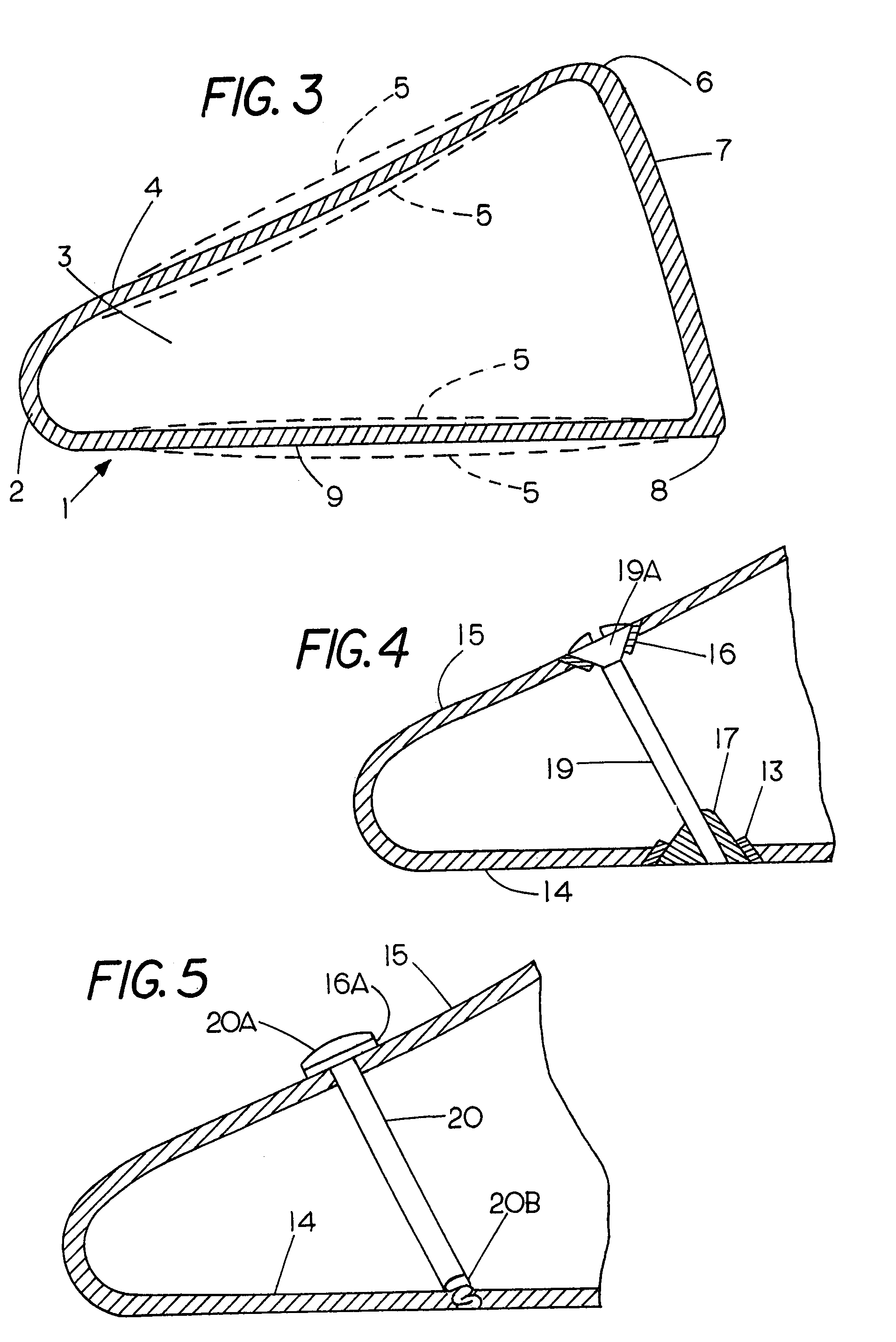
[0029]FIG. 3 is a drawing of a typical large hollow metal golf club head 1 having a face 7 held at edges 6 and 8 to a crown wall 4 and a sole wall 9, respectively. The face is conventionally welded in place. The club head is thus enclosed around the perimeter of the face, as is well known, leaving a hollow interior. The rear 2 of the club head joins the sole 9 and crown 4 and is spaced from the face.

[0030]The dotted lines 5 illustrate the basic mode of crown-sole vibration of the hollow driver head 1, immediately after impact by a ball on the face 7. These vibrations and deflections of the crown and sole cause a sound that can be heard by a golfer. Relatively slight face-rear movement (not shown) accompanies this vibration.

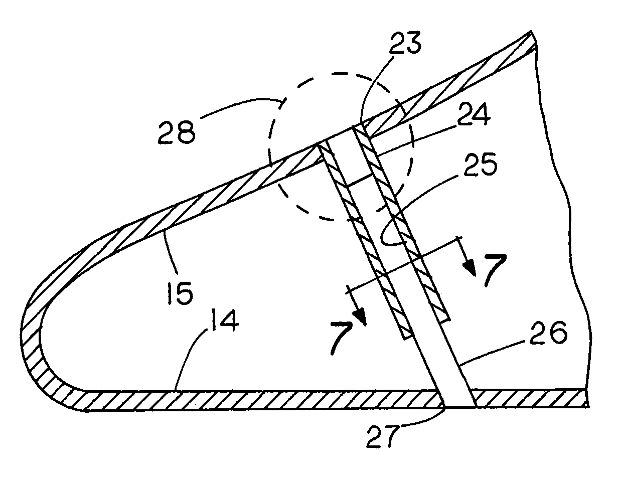
[0031]FIG. 4 fragmentarily shows a rear portion of a hollow golf club head having a sole wall 14 and crown wall 15, with a damping structure between the two walls. The damping structure comprises a screw 19 or other column that has rubber or elastomeric washers 16...


PUM


Abstract

An internal vibration damper for hollow golf club heads is disclosed. Of particular concern is vibration of the club sole and crown when the face of the club impacts a golf ball. At least one column extends from the sole to the crown, approximately perpendicular to the surfaces of the sole and crown. The column construction or its mounting acts to dampen and reduce vibrations of the sole and crown toward and apart from each other upon ball impact on the face of the club head.

Description

BACKGROUND OF THE INVENTION[0001]The present disclosure relates to damping sound and vibration in large hollow golf club heads by providing a damper between the sole and top wall or crown of such golf clubs.[0002]Currently, large, hollow metal driver-type golf club heads typically generate a strong and often objectionable, sharp ringing sound immediately after impact of a face of the club head on a ball. When hollow metal heads first became available, they were often filled with a vibration-damping foam material. This added unwanted weight. What was worse, because of its lack of rigidity, the added weight of the foam did not participate fully in the impact. This caused reduced driving distance. More recently with even larger heads of this type, the ringing sound was allowed by club head designers, even with the objection of some golfers.[0003]Test have shown that the impact of a ball on the club face of a typical modern hollow golf club head produces an amplitude of vibration of the...

Claims


Application Information

Patent Timeline
Patent Type & Authority Patents(United States)
IPC IPC(8): A63B53/04A63B53/06
CPCA63B53/0466A63B53/08A63B59/0092A63B2053/0437A63B2209/00A63B2053/0433A63B2053/0458A63B60/54A63B53/0437A63B53/0433A63B53/0458A63B60/00
Inventor WERNER, FRANK
Owner ORIGIN INC
Why Eureka
Try Eureka