Multi-purpose propulsion device
What is Al technical title?
Al technical title is built by PatSnap Al team. It summarizes the technical point description of the patent document.
a propulsion device and multi-purpose technology, applied in the direction of spring guns, white arms/cold weapons, weapons, etc., can solve the problem that devices may employ more complex systems
Inactive Publication Date: 2008-11-11
SAPIR
View PDF56 Cites 31 Cited by
Summary
Abstract
Description
Claims
Application Information
AI Technical Summary
This helps you quickly interpret patents by identifying the three key elements:
Problems solved by technology
Method used
Benefits of technology
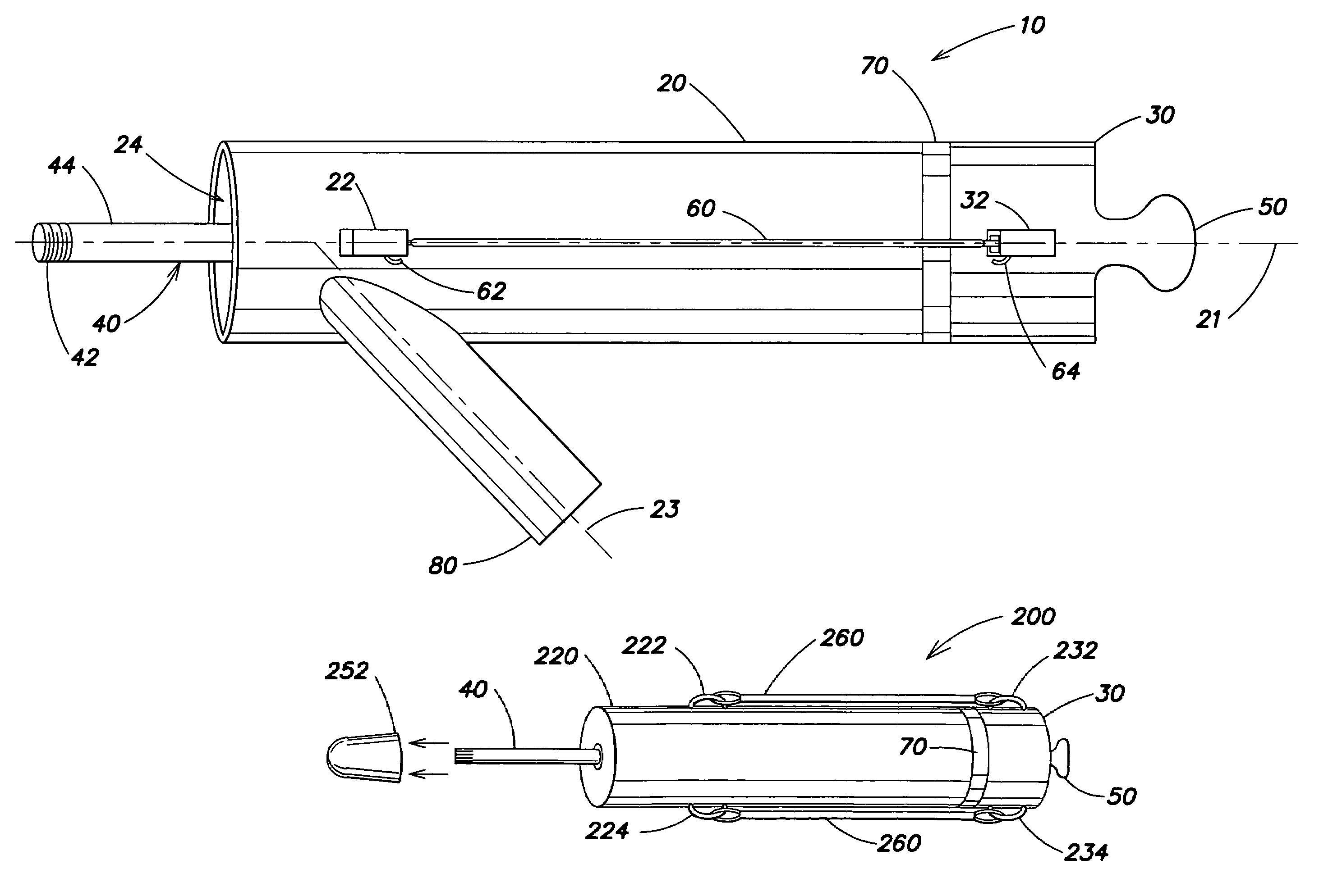
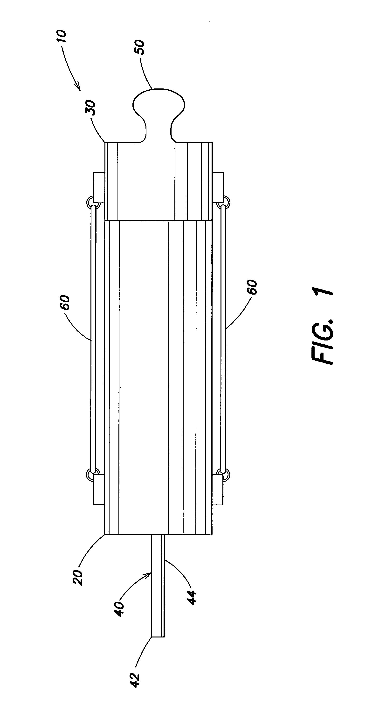
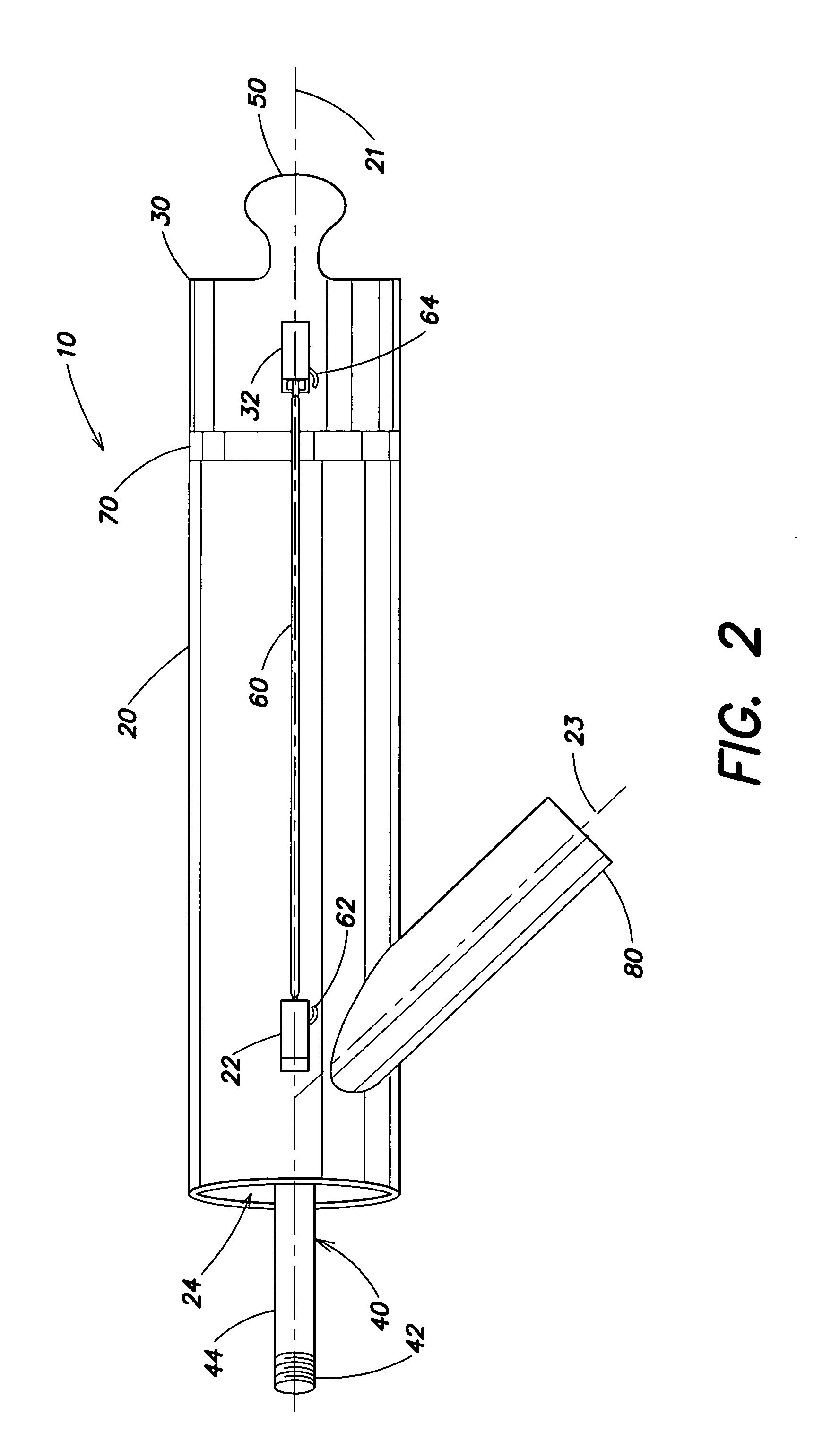
[0004]In another embodiment of this aspect, the device includes a projectile mount configured to hold an object to be projected, and a housing. The device also includes a retractor mechanism coupled by a linkage to the projectile mount for producing movement of the projectile mount relative to the housing. The retractor mechanism has a front face, and the housing has a back face defining a strike plate. The retractor mechanism is axially aligned with the housing, such that the front face of the retractor mechanism is adjacent the strike plate in a first position. The device also includes at least one resilient member coupled to the housing and the retractor mechanism. Relative movement of the front face of the retractor mechanism from the first position to a second position in which the front face of the retractor mechanism is spaced apart from the strike plate stores energy in the at least one resilient member. Release of the retractor mechanism allows the retractor mechanism to return to the first position which transfers the stored energy into movement of the retractor mechanism and the projectile mount.
Problems solved by technology
These devices may employ more complex systems, including compressed air chambers, pistons, triggers, latches, pulleys, springs, or gun powder.
Method used
Image
Click on the blue label to locate the original text in one second.
Reading with bidirectional positioning of images and text.
Examples
Embodiment Construction
[0020]Aspects of the invention relate to a propulsion device having a variety of applications and configurations. In particular, some aspects of the invention relate to a device for projecting or propelling various types of toys or sporting devices into the air, while other aspects of the invention relate to a device which may have a variety of practical uses. For example, the present invention may have survival applications, and military applications, such as the deployment of weapons.
[0021]As will be explained in further detail below, the propulsion device of the present invention typically includes four primary components: a housing, a retractor mechanism, a projectile mount, and one or more resilient members. The projectile mount is coupled to the retractor mechanism for movement in response to the retractor mechanism. The projectile mount holds an object prior to the object being propelled from the device. Once the object is positioned with respect to the mount, the retractor m...
PUM
Abstract
A device for projecting various types of objects is provided. The device includes a projectile mount configured to hold an object for projecting, a housing with a passageway therethrough, and a retractor mechanism coupled to the projectile mount for movement therewith relative to the housing. At least one resilient member is coupled to the housing and the retractor mechanism, such that when the retractor mechanism is drawn away from the housing, the resilient member stores energy, and relative movement of the retractor mechanism back towards the housing transfers the stored energy into movement of the projectile mount and the object. The device may be utilized as a toy, or for various recreational, military, or rescue purposes. Further, by employing an adaptor on the projectile mount, the device may be configured to project a wide variety of sized and shaped objects.
Description
FIELD OF INVENTION[0001]The present invention relates generally to a device for projecting or propelling an object, and more particularly to a device which projects or propels an object using a movable mount.DISCUSSION OF RELATED ART[0002]There are various types of devices that currently exist to propel or project an object through the air. Some examples of such devices include toys or sporting devices like a sling shot, or a bow and arrow. Other recreational and / or military devices are known to project or propel an object through air or water. These devices may employ more complex systems, including compressed air chambers, pistons, triggers, latches, pulleys, springs, or gun powder. Examples of such devices are found in the following patents: U.S. Pat. Nos. 3,579,896; 3,949,731; 4,086,901; 4,165,729; 4,297,985; 5,671,722; 5,979,424; 6,599,161; and 6,742,509.SUMMARY OF INVENTION[0003]In one aspect, a device for projecting an object is disclosed. In one embodiment of this aspect, th...
Claims
Application Information
Patent Timeline
Application Date:The date an application was filed.
Publication Date:The date a patent or application was officially published.
First Publication Date:The earliest publication date of a patent with the same application number.
Issue Date:Publication date of the patent grant document.
PCT Entry Date:The Entry date of PCT National Phase.
Estimated Expiry Date:The statutory expiry date of a patent right according to the Patent Law, and it is the longest term of protection that the patent right can achieve without the termination of the patent right due to other reasons(Term extension factor has been taken into account ).
Invalid Date:Actual expiry date is based on effective date or publication date of legal transaction data of invalid patent.