Variable-geometry intake manifold for an internal-combustion engine

a technology of variable geometry and intake manifold, which is applied in the direction of combustion engines, combustion-air/fuel-air treatment, charge feed systems, etc., can solve the problems of inability to detect, no longer receiving motion, and expensive installation of position sensors used in partialization devices available on the market, so as to achieve easy and economically advantageous production

Inactive Publication Date: 2008-11-25
FAB ITAL MAGNETI MARELLI SPA
View PDF5 Cites 2 Cited by
  • Summary
  • Abstract
  • Description
  • Claims
  • Application Information

AI Technical Summary

Benefits of technology

[0008]The aim of the present invention is to provide a variable-geometry intake manifold for an internal-combustion engine that will be free from the drawbacks described above and, in particular, will be easy and economically advantageous to produce.

Problems solved by technology

However, currently known position sensors used in partialization devices available on the market are costly and complex to install.
In addition, since known position sensors detect the angular position of the common shaft, they do not detect directly the actual position of the partialization bodies and hence are not able to detect whether, on account of a mechanical problem, one of the partialization bodies no longer receives motion from the actuator device.
Finally, on account of their dimensions, known position sensors are suitable for being coupled to the common shaft, but are not suitable for being coupled to a single partialization body to determine directly the actual position of the partialization body itself.

Method used


Image

  • Variable-geometry intake manifold for an internal-combustion engine
  • Variable-geometry intake manifold for an internal-combustion engine
  • Variable-geometry intake manifold for an internal-combustion engine

Examples


Embodiment Construction

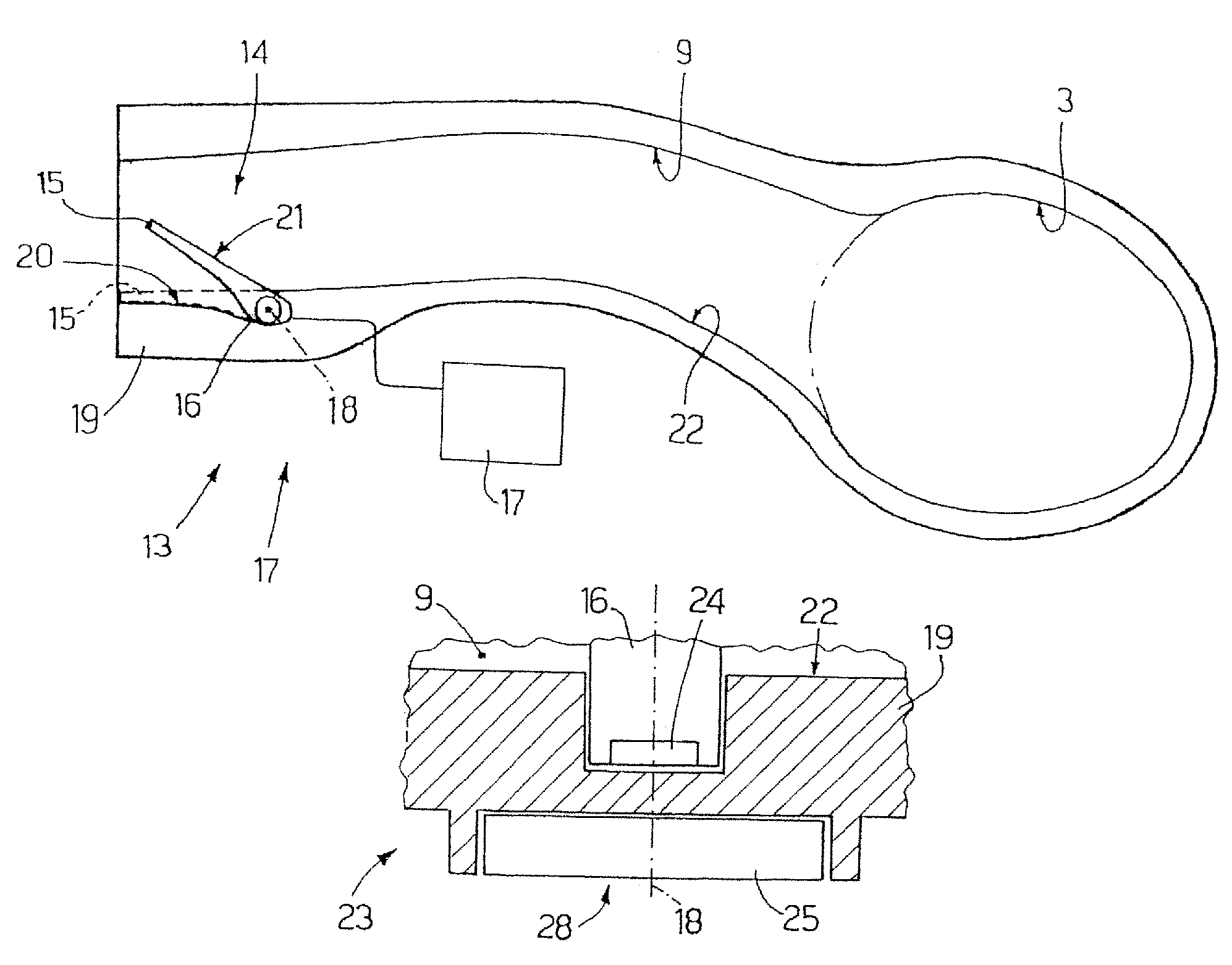
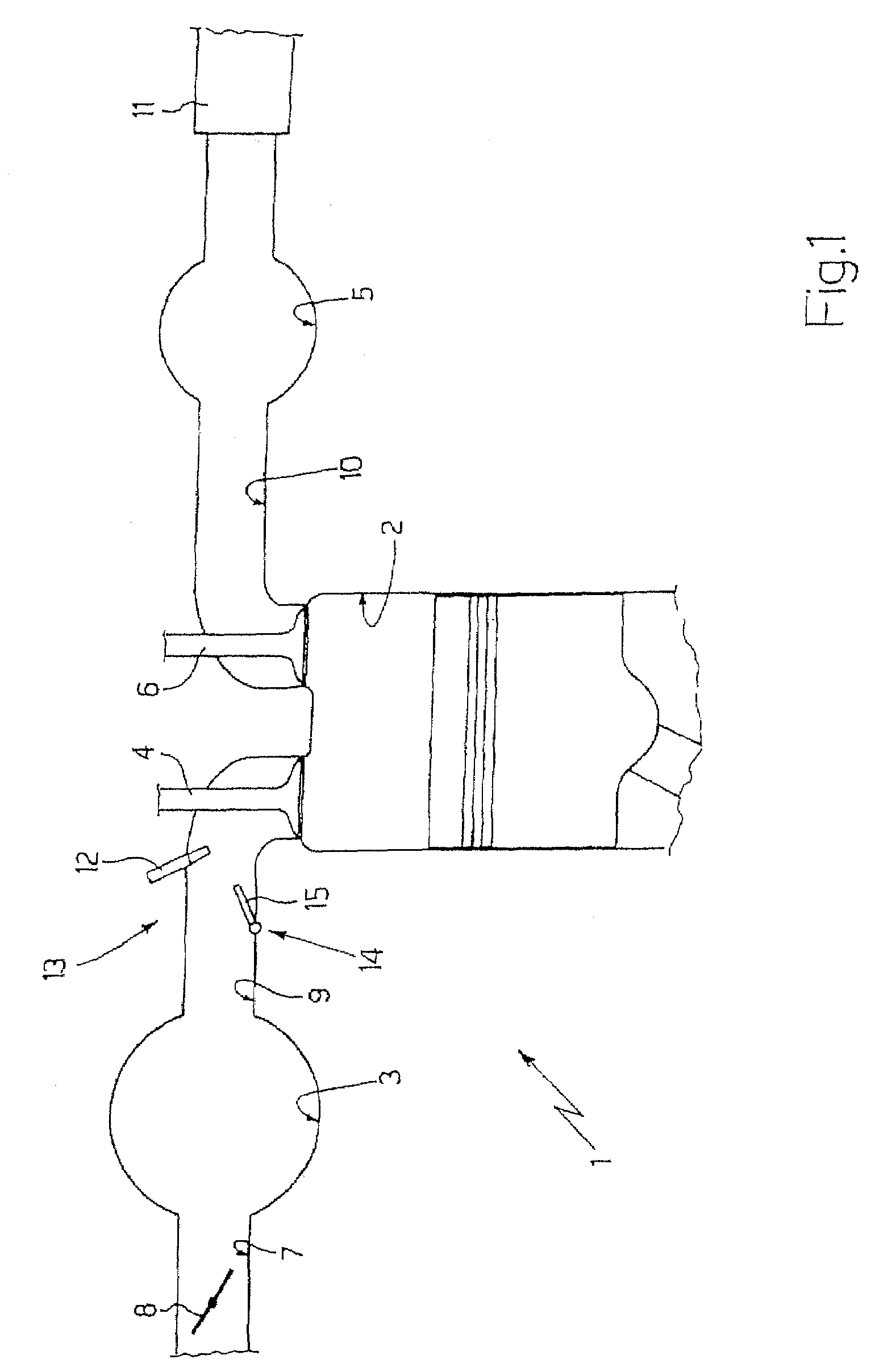
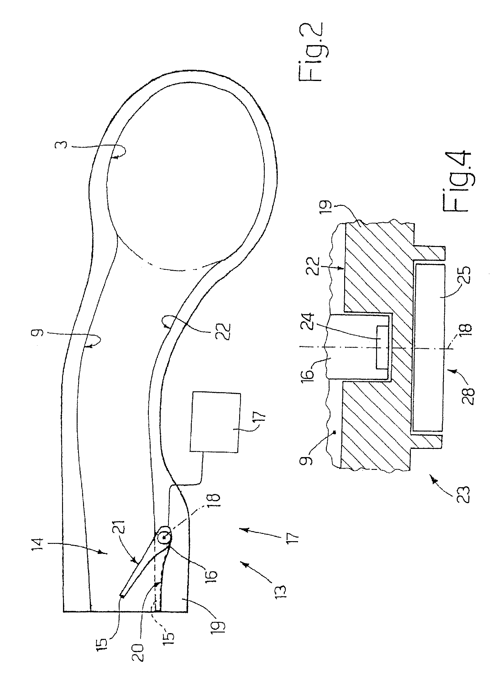
[0017]In FIG. 1, the reference number 1 designates as a whole an internal-combustion engine provided with four cylinders 2 (only one of which is illustrated in FIG. 1), each of which is connected to an intake manifold 3 via at least one intake valve 4 and to an exhaust manifold 5 via at least one exhaust valve 6.

[0018]The intake manifold 3 receives fresh air (i.e., air coming from the outside environment) through a supply pipe 7 regulated by a throttle valve 8 and is connected to the cylinders 2 by means of respective intake pipes 9 (only one of which is illustrated in FIG. 1), each of which is regulated by the corresponding intake valve 4. Likewise, the exhaust manifold 5 is connected to the cylinders 2 by means of respective exhaust pipes 10 (only one of which is illustrated in FIG. 1), each of which is regulated by the corresponding exhaust valve 6. Stemming from the exhaust manifold 5 is an outlet pipe 11, which terminates with a muffler (known and not illustrated) for introduci...


PUM


Abstract

Described herein is a variable-geometry intake manifold for an internal-combustion engine; the intake manifold is provided with: at least one intake pipe, which connects the intake manifold to at least one cylinder of the internal-combustion engine; a partialization device for varying the geometry of the intake manifold that has at least one partialization body, which is set inside the intake pipe and is provided with a shaft mounted so that it can rotate about an axis of rotation; and at least one angular-position sensor, which is designed to determine the angular position of the shaft about the axis of rotation and has a permanent magnet fixed on the shaft, and a reader, which is designed to read the orientation of the permanent magnet and is set on the outside of the intake pipe in the proximity of a wall of the intake pipe itself and in the proximity of the permanent magnet.

Description

TECHNICAL FIELD[0001]The present invention relates to a variable-geometry intake manifold for an internal-combustion engine.BACKGROUND ART[0002]An internal-combustion engine is provided with a number of cylinders, each of which is connected to an intake manifold via at least one intake valve and to an exhaust manifold via at least one exhaust valve. The intake manifold receives fresh air (i.e., air coming form the outside environment) through a supply pipe provided with a throttle valve and is connected to the cylinders by means of respective intake pipes, each of which terminates in a position corresponding to at least one intake valve.[0003]In a modern internal-combustion engine, the intake manifold can be of the variable-geometry type; i.e., it can be provided with a partialization device, which varies the cross section of the intake pipes as a function of the engine regime (i.e., the r.p.m. of the engine shaft). At low r.p.m. the section of passage of the air through the intake ...

Claims


Application Information

Patent Timeline
Patent Type & Authority Patents(United States)
IPC IPC(8): F02B31/00
CPCF02B31/06F02D9/103F02D9/105Y02T10/146Y02T10/12
Inventor LANCIONI, FEDERICOPECORA, MICHELE
Owner FAB ITAL MAGNETI MARELLI SPA
Why Eureka
Try Eureka