Side lock apparatus

a side lock and locking device technology, applied in the direction of mechanical devices, passenger space, lock applications, etc., can solve the problems of different operating strokes of the rods, the lid cannot be opened and closed in a smooth fashion, etc., and achieve the effect of smooth implementation, convenient operation and secure operation

Active Publication Date: 2008-11-25
PIOLAX CO LTD
View PDF7 Cites 44 Cited by
  • Summary
  • Abstract
  • Description
  • Claims
  • Application Information

AI Technical Summary

Benefits of technology

[0008]An object of the invention is to provide a side lock apparatus which enables the implementation of smooth opening, closing and locking operations of the lid by causing the pair of rods to follow properly the operation of the knob for smooth operation thereof.

Problems solved by technology

In the case of the side lock apparatus disclosed in JP-A-2004-211383 above, however, since the other sliding member is caused to slide via the pinion gear as a result of interlinkage with the sliding of the one of the sliding members, there has occurred a case where the lid cannot be opened and closed in a smooth fashion.
In addition, in the event that there exists a play or looseness between the rack groove and the pinion gear, there is caused a difference in operating stroke between the pair of rods, and in this case, too, there is caused a problem with the opening and closing operation of the lid.

Method used


Image

  • Side lock apparatus
  • Side lock apparatus
  • Side lock apparatus

Examples


Embodiment Construction

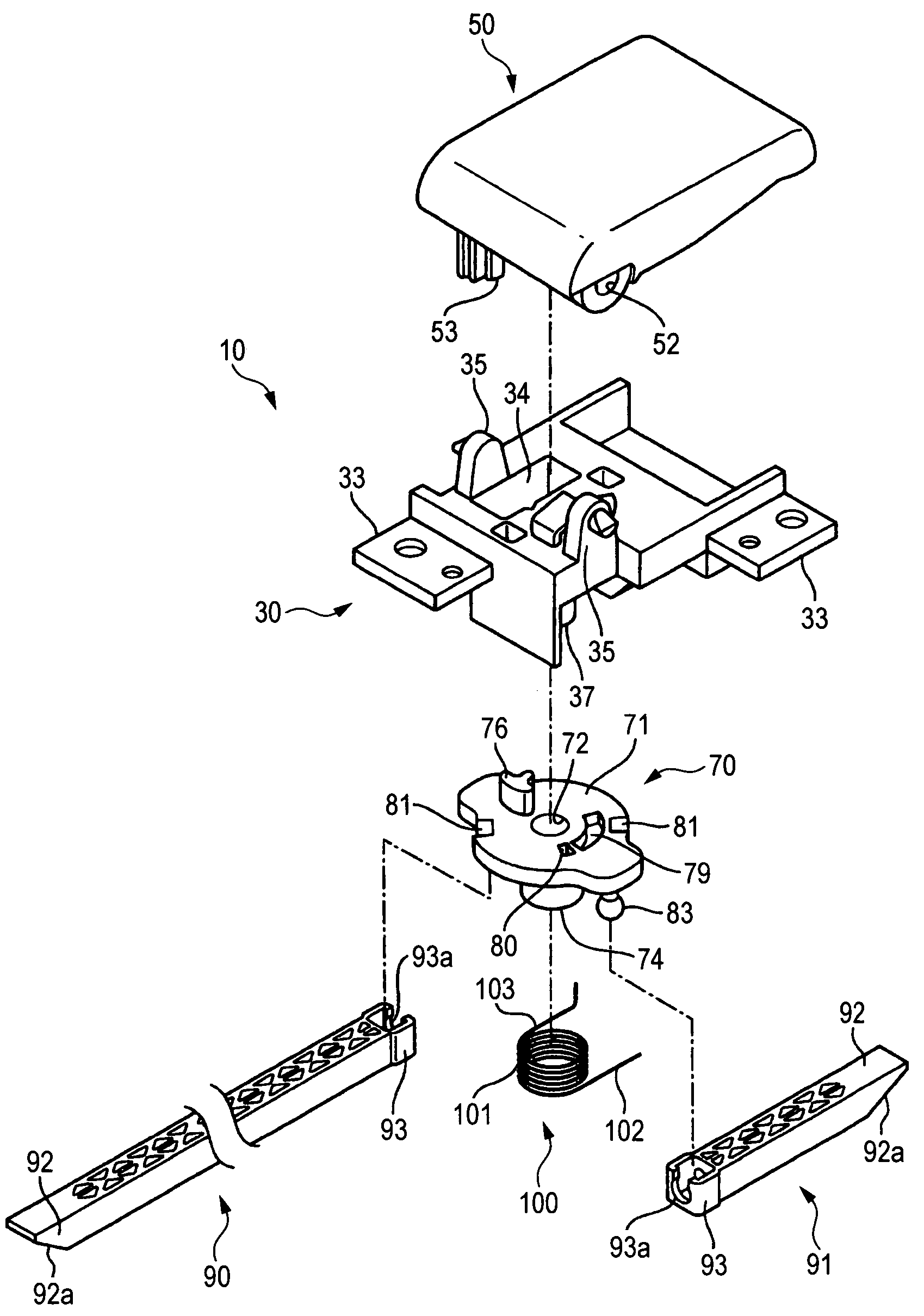
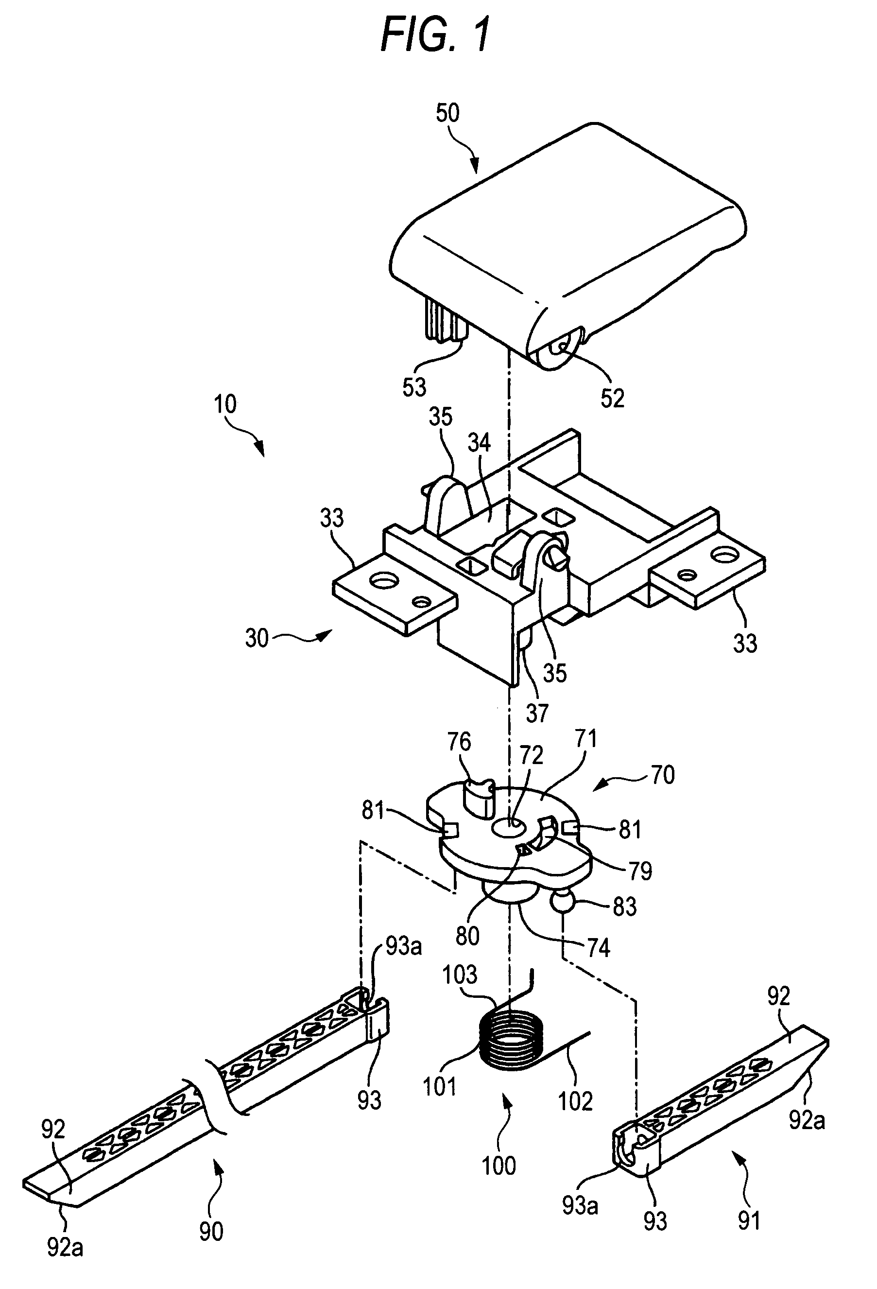
[0040]Hereinafter, referring to FIGS. 1 to 11, an embodiment of a side lock apparatus of the invention will be described.

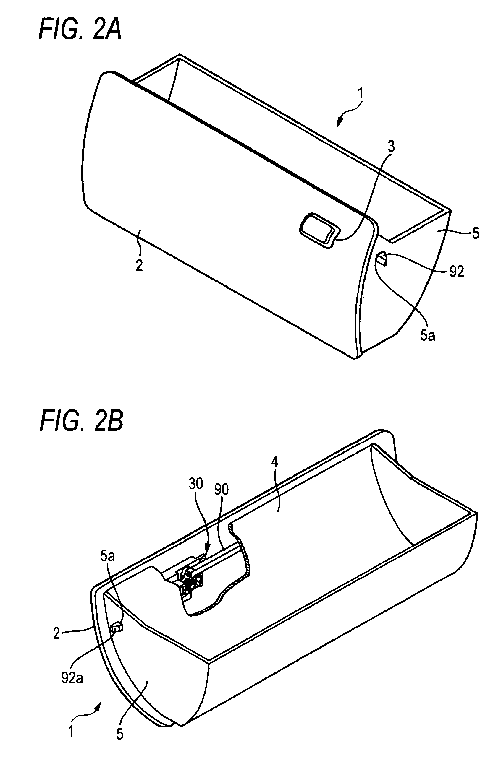
[0041]This side lock apparatus is applied to, for example, a lid 2 for a box-shaped glove box 1 provided in an opening in an instrument panel of a motor vehicle (refer to FIGS. 2A and 2B). Support shafts or the like, not shown, are provided in lower positions on both ends of the glove box 1 in such a manner as to protrude therefrom, and the support shafts so provided are then inserted into shaft holes, not shown, which are provided in lower positions on both ends of an opening 6 (refer to FIGS. 9, 10) in the instrument panel, whereby the lid 2 of the glove box 1 is made to cover and uncover the opening 6. A mounting opening 3 which passes through the lid 2 is provided at a predetermined location on the lid, and a side lock apparatus 10 of the invention is mounted in this mounting opening 3.

[0042]Note that in the case of this embodiment, while the side lock apparat...


PUM


Abstract

A side lock apparatus comprises a retainer, a rotor rotatably supported on the retainer, a pair of rods which are brought into engagement with positions which are point symmetrical relative to an axial center of the rotor at proximal end portions thereof and are supported in such a manner that distal end portions thereof appear from and disappear into both ends of a lid so as to be brought into engagement with and disengagement from a circumferential edge of an opening, a knob supported on the retainer in such a manner as to be pushed and pulled on and a return spring mounted on the rotor. When the knob is pulled on, since a pusher element of the knob pushes on a bearing portion of the rotor, the rotor rotates against the biasing force of the return spring, whereby the rods are withdrawn into the inside of the lid.

Description

[0001]This application is based on Japanese Patent Application No. 2005-289959, which is incorporated herein by reference.BACKGROUND OF THE INVENTION[0002]1. Field of the Invention[0003]The present invention relates to, for example, a side lock apparatus which locks a lid provided in an opening in a motor vehicle in a closed state or releases the lock to open the lid.[0004]2. Description of the Related Art[0005]A glove box is provided on a passenger seat side of an instrument panel of a motor vehicle. A lid of this glove box is mounted in such a manner as to cover and uncover an opening in the instrument panel, and furthermore, a lock apparatus is provided which locks the lid in a closed state and releases the lock to open the lid.[0006]As the lock apparatus of this type, there are known a center-lock type lock apparatus and a side-lock type lock apparatus. As the side-lock type lock apparatus, a side lock apparatus is disclosed in JP-A-2004-211383 below which has a case, a knob rot...

Claims


Application Information

Patent Timeline
Patent Type & Authority Patents(United States)
IPC IPC(8): E05C1/06E05B63/14B60R7/06E05B63/22E05B83/30E05B85/22E05C9/02E05C9/10
CPCE05B83/30E05C9/043Y10T292/0839Y10T292/0837
Inventor OOKAWARA, TOSHIHIKO
Owner PIOLAX CO LTD
Why Eureka
Try Eureka