Polymer coated guide wire

a polymer coating and guide wire technology, applied in the field of guide wires, can solve the problems of affecting the ability of physicians to safely and controllably advance the guidewire, and the difficulty of using conventional guidewires using tapered distal core sections as discussed above, and achieve the effect of sufficient radiopacity

Inactive Publication Date: 2008-11-25
ABBOTT CARDIOVASCULAR
View PDF183 Cites 66 Cited by
  • Summary
  • Abstract
  • Description
  • Claims
  • Application Information

AI Technical Summary

Benefits of technology

[0015]The guidewire of the invention provides the enhanced distal and proximal support needed for stent deployment, advancement of atherectomy devices and the like and provides a smooth transition between the proximal core section and the flattened distal tip of the core member while exhibiting excellent steerability.
[0023]A core member with a linear change in stiffness over its length provides improved advancement and control of the distal end of an intracorporeal device through a patient's body lumen. The improvement in handling characteristics results in part from the absence of abrupt changes in flexibility that can obscure the tactile feedback to the physician holding the proximal end of the device. In addition, the abrupt changes in stiffness can cause the device to resist smooth and controllable advancement because a step or threshold force must be applied to overcome the abrupt change in stiffness.
[0027]In one embodiment, the flexible body member of the guidewire of the present invention is a multi-layered member formed with at least one layer of a polymer material and one layer of radiopaque material. If there are two polymer layers, the radiopaque layer is preferably disposed between the two polymer layers. The radiopaque layer may be continuous or intermittent and comprises elements which have regular or irregular repetitions. The radiopaque layer may also be in the form of an open helical ribbon with one or more adjacent turns of the helical ribbon which do not touch. The helical ribbon is held in place by one or more polymer layers. The radiopaque layer can have sufficient radiopacity to be visualized under a fluoroscope, allowing the physician to use the radiopaque layer not only as a reference tool while advancing the guidewire to a desired intraluminal location, but also as a measuring guide for determining the size of lesions.

Problems solved by technology

Conventional guidewires using tapered distal core sections as discussed above can be difficult to use in many clinical circumstances because they have an abrupt stiffness change along the length of the guidewire, particularly where the tapered portion begins and ends.
The abrupt change in resistance felt by the physician can hinder the physician's ability to safely and controllably advance the guidewire through the vasculature.

Method used


Image

  • Polymer coated guide wire
  • Polymer coated guide wire
  • Polymer coated guide wire

Examples


Embodiment Construction

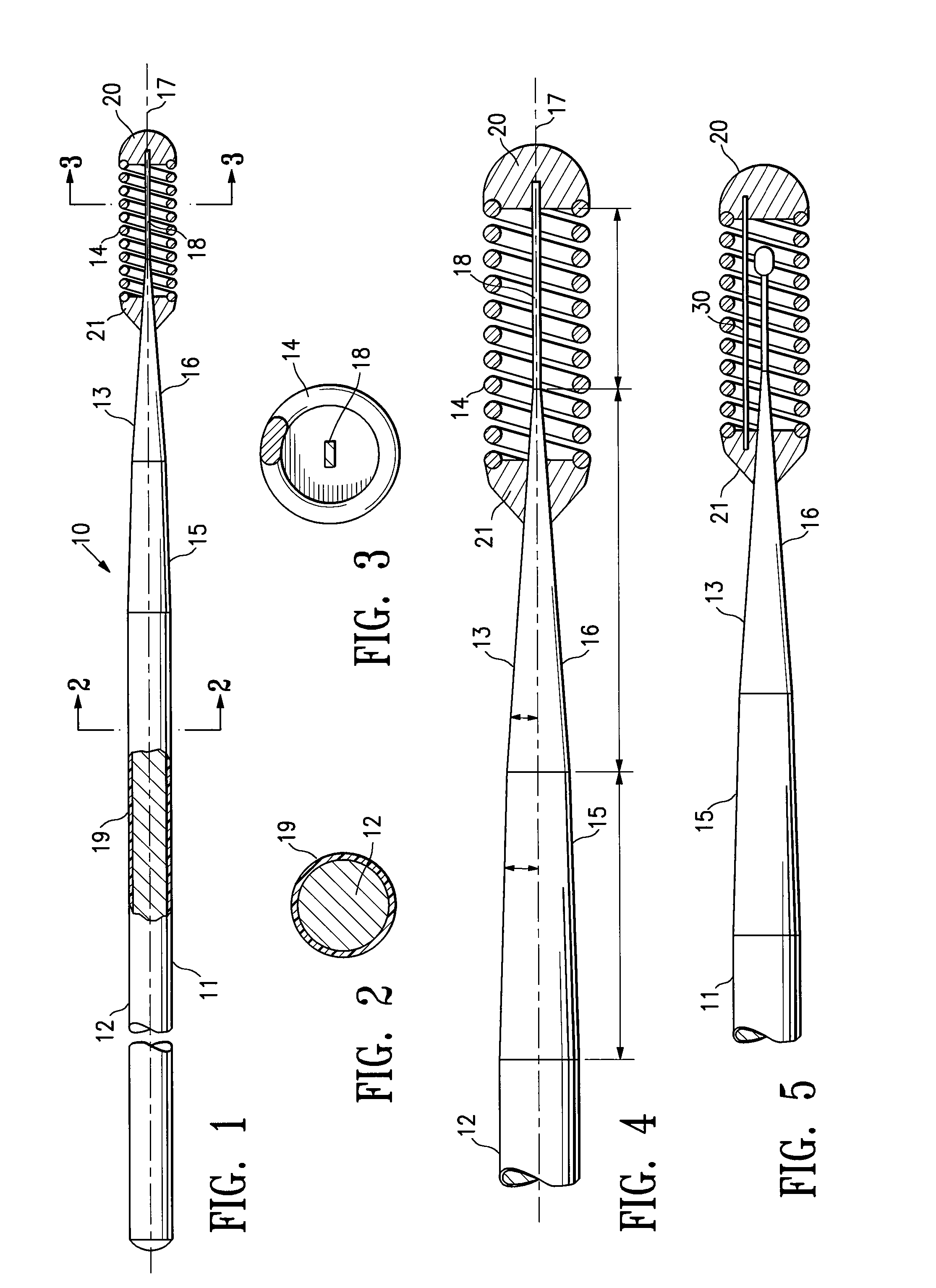
[0081]FIGS. 1-3 depict a guidewire 10 having features of the invention which has a core member 11 with a proximal core section 12, a distal core section 13 and a helical coil 14. The distal core section 13 has a first tapered segment 15 and a second tapered core segment 16 which is distally contiguous to the first tapered core segment. The second tapered segment 16 tapers at a greater degree than the first tapered segment and this additional taper provides a much smoother transition when the distal portion of the guidewire 10 is advanced through a tortuous passageway. The degree of taper of the first tapered core segment 15, i.e. the angle between the longitudinal axis 17 and a line tangent to the first tapered core segment 15 is about 2° to about 10°, whereas the taper of the second tapered core segment 16, i.e. the angle between the longitudinal axis and the second tapered core segment is larger than the first angle and is about 5° to about 10° such as is shown in the enlarged vie...


PUM

PropertyMeasurementUnit
lengthaaaaaaaaaa
widthaaaaaaaaaa
widthaaaaaaaaaa

Abstract

A guidewire or section thereof, that has a core member or the like with a plurality of contiguous tapered segments having taper angles that are configured to produce a linear change in stiffness over a longitudinal portion of the device. The device may also have a core section with a continuously changing taper angle to produce a curvilinear profile that is configured to produce a linear change in stiffness of the core over a longitudinal portion of the device. An embodiment has a plurality of radiopaque elements that may be intermittent, continuous or in the form of a helical ribbon for scaled measurement of intracorporeal structure under flouroscopic imaging. Another embodiment has at least one layer of polymer over the distal end of the device.

Description

CROSS-REFERENCE TO RELATED APPLICATIONS[0001]This is a divisional application of a parent application having U.S. Ser. No. 10 / 631,275, filed Jul. 31, 2003, which is a divisional application of U.S. Ser. No. 09 / 441,698, filed Nov. 16, 1999, now U.S. Pat. No. 6,673,025, which is a continuation-in-part application of U.S. Ser. No. 09 / 203,140, filed Dec. 1, 1998, now U.S. Pat. No. 6,390,993, which is a continuation-in-part application of U.S. Ser. No. 08 / 868,764, filed Jun. 4, 1997, now abandoned, the contents of all of which are hereby incorporated by reference.BACKGROUND[0002]This invention relates to the field of guidewires for advancing intraluminal devices such as stent delivery catheters, balloon dilatation catheters, atherectomy catheters and the like within a patient's body, specifically, within a patient's vasculature.[0003]In a typical percutaneous procedure in a patient's coronary system, a guiding catheter having a preformed distal tip is percutaneously introduced into a pat...

Claims


Application Information

Patent Timeline
Patent Type & Authority Patents(United States)
IPC IPC(8): A61B5/00A61M25/00
CPCA61L31/10A61L31/18A61M25/09A61M25/0045A61M25/0054A61M2025/09083A61M2025/09133A61M2025/09166
Inventor RICHARDSON, MARK T.ANDERSON, DAVID M.BIAGTAN, EMMANUEL C.BRENNAN, LAWRENCE E.BURKETT, DAVID H.CORNISH, WAYNE E.ESSELSTEIN, ROBERT C.JACOBS, JAMESJALISI, MARC M.MIRZAEE, DARYUSH P.PALMER, OLIN J.SCHREINER, JOHNSTALKER, KENT C.
Owner ABBOTT CARDIOVASCULAR
Why Eureka
Try Eureka