Supercharge Your Innovation With Domain-Expert AI Agents!

On-die coupled inductor structures for improving quality factor

a technology of inductor structure and quality factor, which is applied in the direction of electric variable regulation, process and machine control, instruments, etc., can solve the problems of coupling inductors and reducing the quality factor (q) of the structur

Active Publication Date: 2008-11-25
APPLE INC
View PDF3 Cites 0 Cited by
  • Summary
  • Abstract
  • Description
  • Claims
  • Application Information

AI Technical Summary

Benefits of technology

The invention relates to techniques and structures for implementing on-die coupled inductor structures that reduce current crowding effects. Current crowding occurs when there is a concentration of current within a small portion of a circuit, which increases the resistance of the circuit. The invention proposes a solution by using multiple narrower parallel strips instead of a single wider strip, which reduces the occurrence of current crowding. The invention also includes 90 degree bends in the inductor structure, which further enhances the quality factor (Q) of the structure. The technical effect of the invention is to improve the performance of on-die coupled inductor structures by reducing current crowding effects and achieving a relatively high Q.

Problems solved by technology

When implemented on-die, coupled inductors have been known to suffer from current crowding effects that reduce the quality factor (Q) of the structures.

Method used


Image

  • On-die coupled inductor structures for improving quality factor
  • On-die coupled inductor structures for improving quality factor
  • On-die coupled inductor structures for improving quality factor

Examples


Embodiment Construction

[0011]In the following detailed description, reference is made to the accompanying drawings that show, by way of illustration, specific embodiments in which the invention may be practiced. These embodiments are described in sufficient detail to enable those skilled in the art to practice the invention. It is to be understood that the various embodiments of the invention, although different, are not necessarily mutually exclusive. For example, a particular feature, structure, or characteristic described herein in connection with one embodiment may be implemented within other embodiments without departing from the spirit and scope of the invention. In addition, it is to be understood that the location or arrangement of individual elements within each disclosed embodiment may be modified without departing from the spirit and scope of the invention. The following detailed description is, therefore, not to be taken in a limiting sense, and the scope of the present invention is defined on...


PUM

PropertyMeasurementUnit
conductiveaaaaaaaaaa
lengthaaaaaaaaaa
path lengthaaaaaaaaaa

Abstract

On-die coupled inductor structures are disclosed that are capable of reducing the occurrence of charge crowding within the structure.

Description

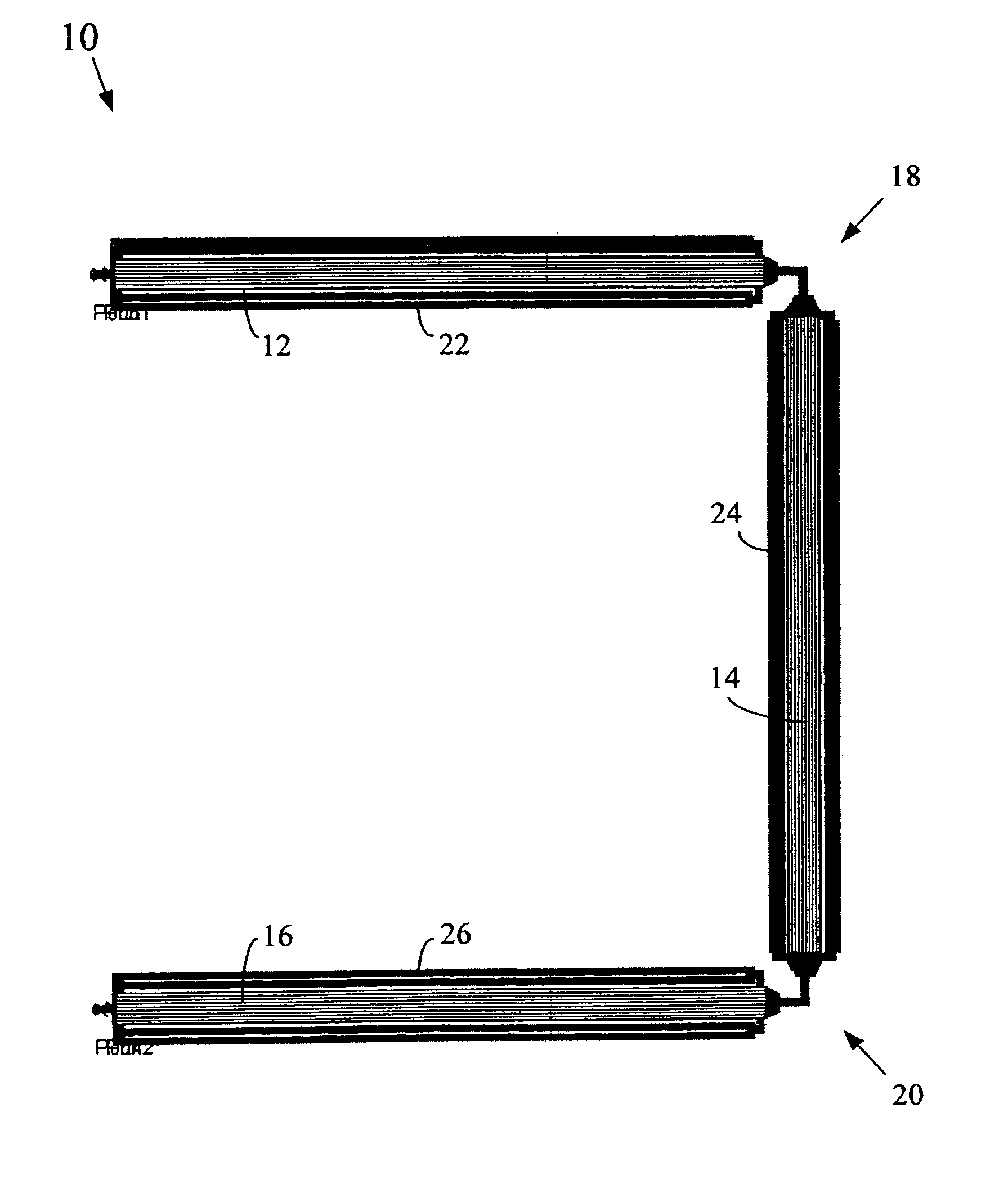
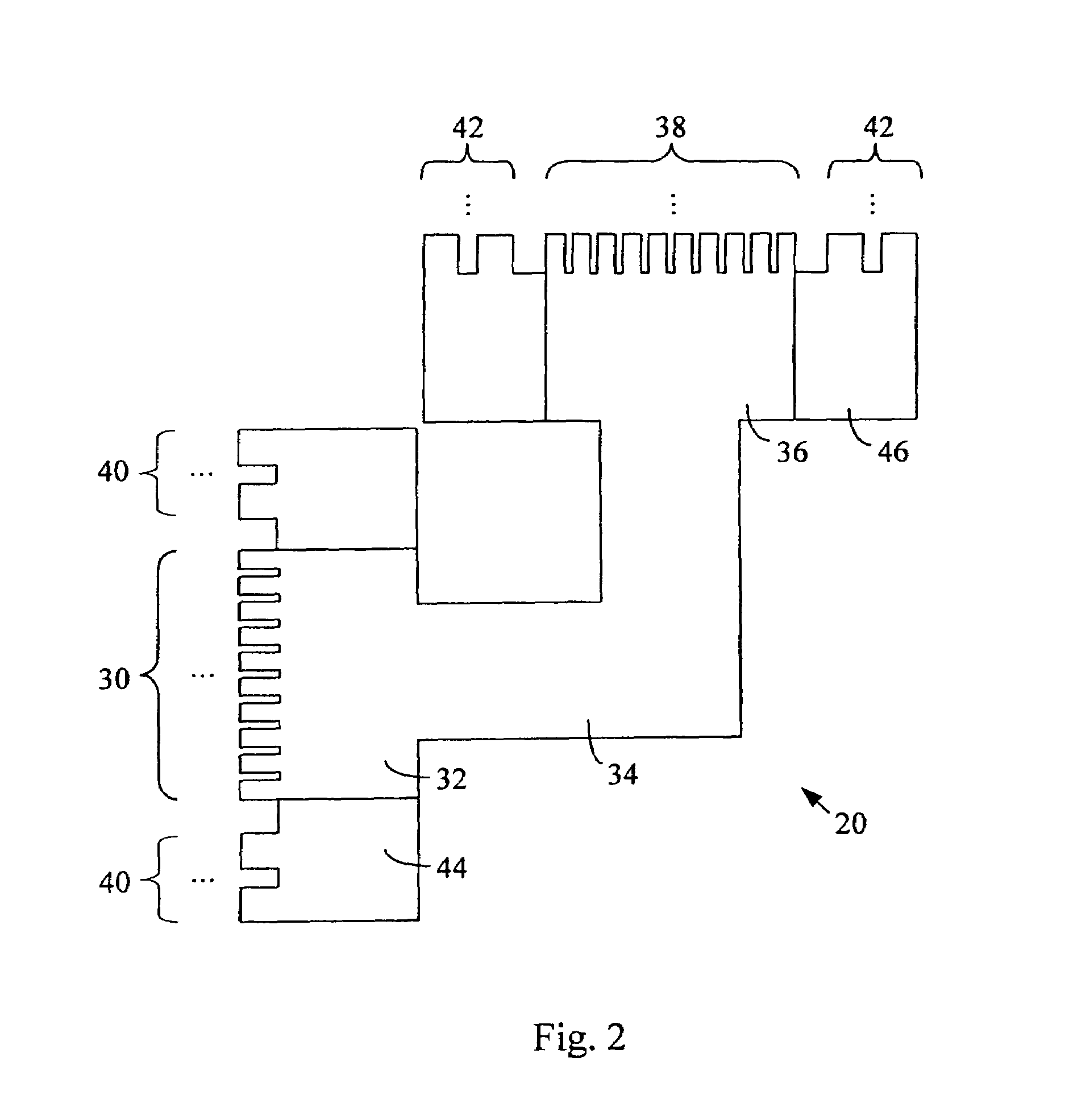
TECHNICAL FIELD[0001]The invention relates generally to microelectronic circuits and, more particularly, to on-die coupled inductor structures.BACKGROUND OF THE INVENTION[0002]Coupled inductors are used in many radio frequency (RF) circuit designs, including low noise amplifiers (LNAs), mixers, power amplifiers, and others. When implemented on-die, coupled inductors have been known to suffer from current crowding effects that reduce the quality factor (Q) of the structures. That is, the current flowing through a portion of the circuit metallization may be concentrated within less than the overall cross section of the metal in a manner that increases the relative loss (resistance) of the circuit. Circuit techniques and structures are needed that are capable of reducing the occurrence of current crowding in on-die coupled inductors.BRIEF DESCRIPTION OF THE DRAWINGS[0003]FIG. 1 is a top view of an exemplary coupled inductor structure in accordance with an embodiment of the present inve...

Claims


Application Information

Patent Timeline
Patent Type & Authority Patents(United States)
IPC IPC(8): H01F5/00
CPCH01L23/5227H01F17/0006H01L2924/3011H01L2924/0002H01L2924/00
Inventor ELMALA, MOSTAFAPARAMESH, JEYANANDH K
Owner APPLE INC
Features
  • R&D
  • Intellectual Property
  • Life Sciences
  • Materials
  • Tech Scout
  • Unparalleled Data Quality
  • Higher Quality Content
  • 60% Fewer Hallucinations
Learn More