
Embroidery sewing machine

a sewing machine and embroidery technology, applied in the field of embroidery sewing machines, can solve the problem that the stitching cannot be substantially carried out, and achieve the effect of reducing the difficulty of stitching

Active Publication Date: 2008-12-02
BROTHER KOGYO KK
View PDF21 Cites 15 Cited by
  • Summary
  • Abstract
  • Description
  • Claims
  • Application Information

AI Technical Summary

Benefits of technology

The present disclosure provides an embroidery sewing machine that can carry out the quilting stitch without being interrupted by the carriage and form an embroidery pattern by the use of an embroidery frame. The machine has a carriage that can hold the embroidery frame and transfer it to a predetermined position. The machine has a drive unit that moves the carriage and a sewing machine motor that drives the needle. The machine can switch between an embroidery sewing mode and a manual-feed sewing mode. In the embroidery sewing mode, the machine sews the embroidery pattern, while in the manual-feed sewing mode, the machine moves the quilting cloth to the predetermined position while the operator carries out the quilting stitch. The machine also has a mode switching unit that selectively switches between the embroidery sewing mode and the manual-feed sewing mode. This allows the operator to carry out the quilting stitch without being interrupted by the carriage while manually moving the quilting cloth in any direction using a sufficient working space.

Problems solved by technology

However, since the carriage is moved upon drive of the needlebar, the carriage stands in the way when the operator moves the quilting cloth, whereupon the quilting stitch cannot substantially be carried out.

Method used


Image

  • Embroidery sewing machine
  • Embroidery sewing machine
  • Embroidery sewing machine

Examples


Embodiment Construction

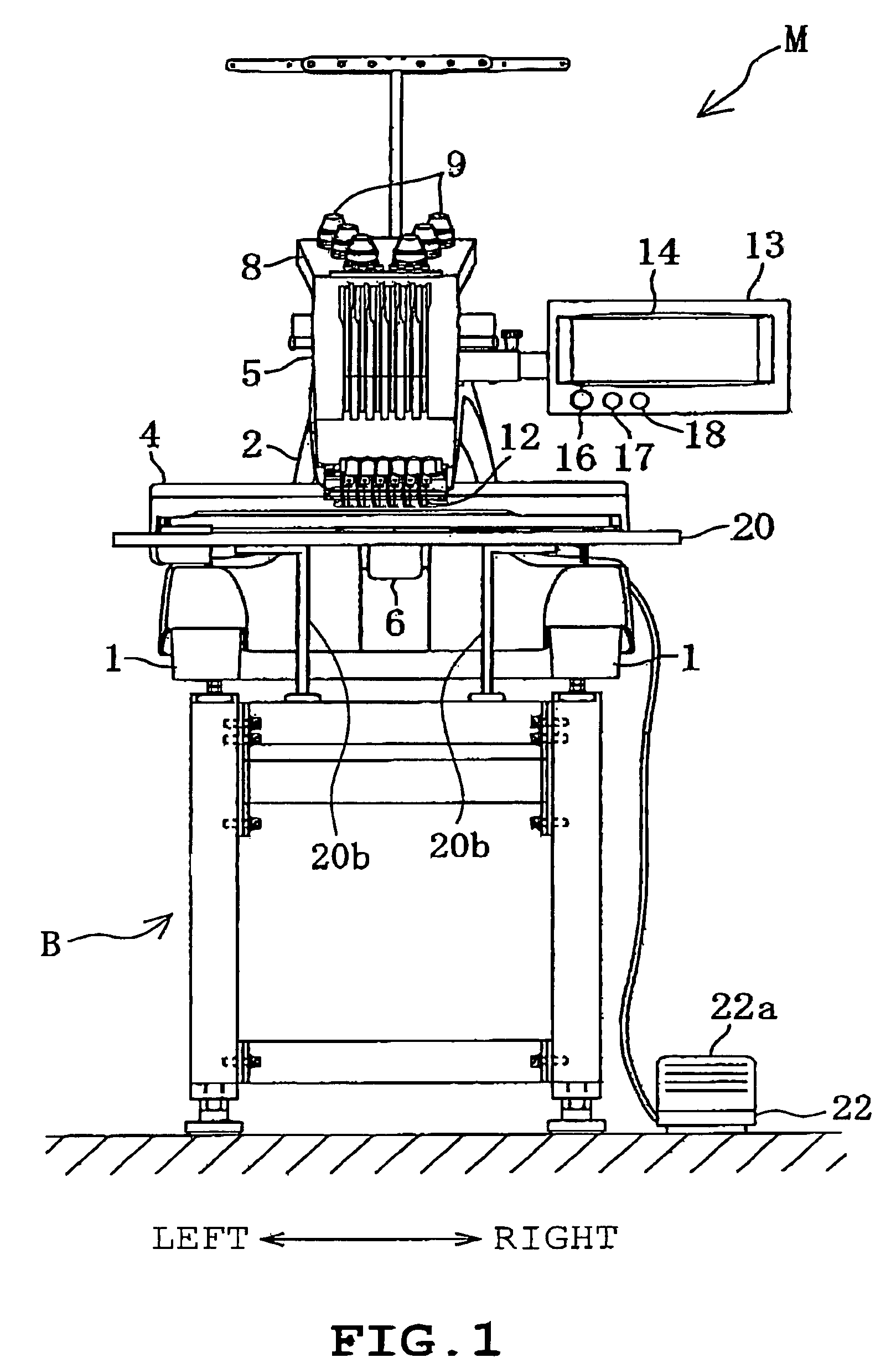
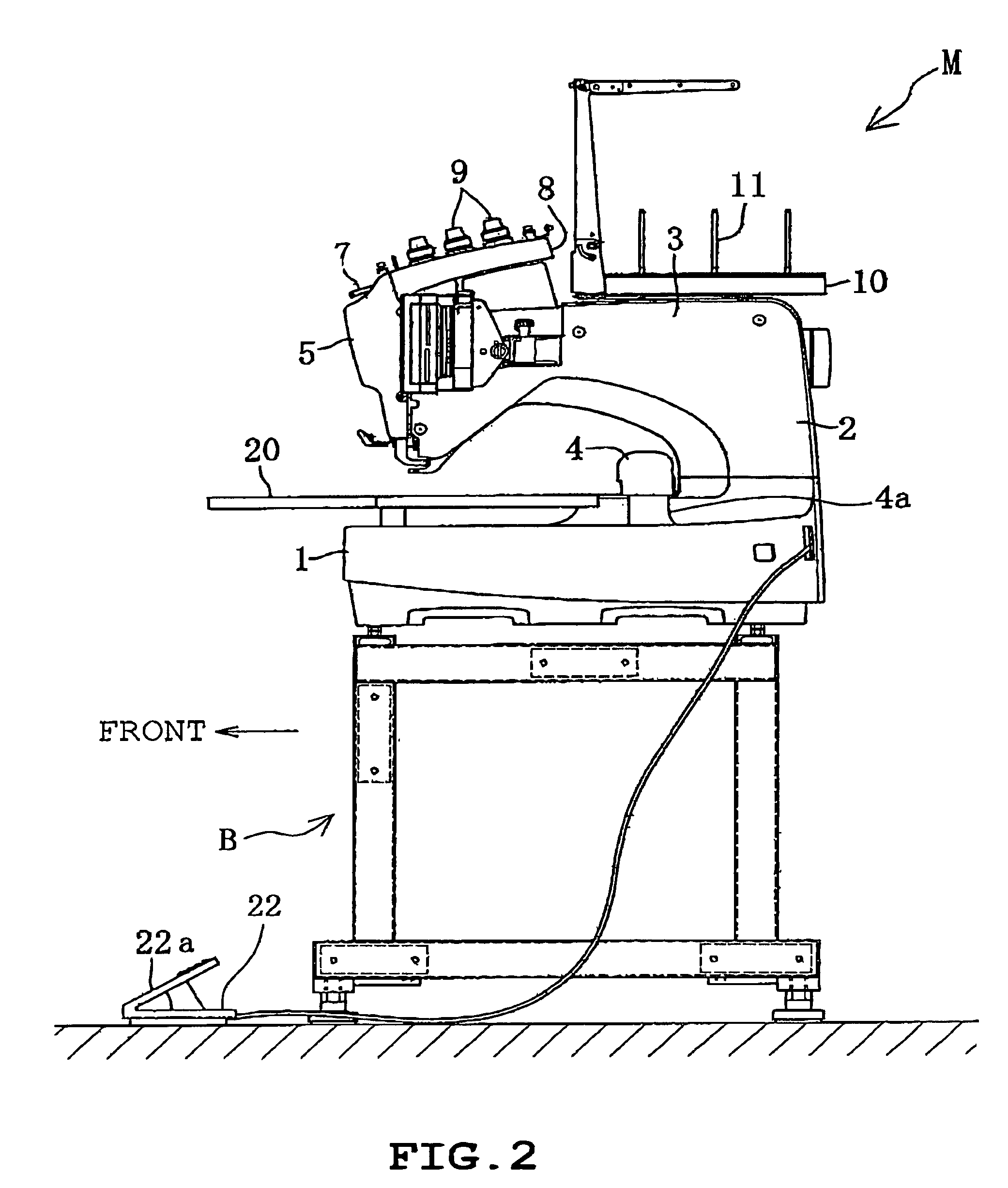
[0027]A first illustrative example of the disclosure will be described with reference to FIGS. 1 to 8. The disclosure is applied to a multineedle embroidery sewing machine M in the example. Referring to FIGS. 1 and 2, the multineedle embroidery sewing machine M includes a pair of legs 1, a sewing pillar 2 standing at rear ends of the legs 1 and a sewing arm 3 protruding frontward from the top of the pillar 2. The multineedle embroidery sewing machine M is mounted on a mounting stand B installed on the floor.

[0028]The legs 1 have a pair of guide grooves 1a (see FIG. 3) which are formed in upper surfaces so as to extend in the front-rear direction, respectively. A carriage 4, which is elongate in the front-rear direction, has right and left ends provided with a pair of leg members 4a (only one is shown in FIG. 2) respectively. The leg members 4a are inserted through the guide grooves 1a from above so as to be guided along the guide grooves 1a in the front-rear direction respectively.

[...


PUM


Abstract

An embroidery sewing machine includes an embroidery frame, a carriage transferring the embroidery frame, a drive unit moving the carriage, a sewing machine motor, a control unit controlling the drive unit and the motor so that an embroidery sewing mode is executed in which an embroidery pattern is sewn or a manual-feed sewing mode is executed in which a sewing operation is carried out with manual cloth feed while the carriage is moved to and held at a predetermined evacuative position, a foot controller, a connecting part connecting the foot controller to the control unit, and a mode switching unit which selectively switches between the embroidery sewing mode and the manual feed sewing mode. The mode switching unit switches to the embroidery sewing mode when the foot controller is non-connected to the connecting part, and to the manual-feed sewing mode when the foot controller is connected to the connecting part.

Description

CROSS-REFERENCE TO RELATED APPLICATIONS[0001]This application is based upon and claims the benefit of priority from the prior Japanese Patent Application No. 2006-56087 filed on Mar. 2, 2006, the entire contents of which are incorporated herein by reference.BACKGROUND[0002]1. Technical Field[0003]The present invention relates to an embroidery sewing machine which can carry out embroidery sewing on workpiece cloth set on an embroidery frame based on embroidery data of embroidery pattern and a quilting sewing by free motion without using the embroidery frame.[0004]2. Description of the Related Art[0005]Embroidery sewing machines comprising a carriage and an embroidery frame have conventionally been used widely. The embroidery frame is attached to the carriage to hold workpiece cloth to be sewn. The carriage and the embroidery frame are moved so that a desired embroidery pattern is formed on the workpiece cloth. The embroidery sewing machine comprises an X-axis driving mechanism and a ...

Claims


Application Information

Patent Timeline
Patent Type & Authority Patents(United States)
IPC IPC(8): D05C5/02
CPCD05B19/08D05B19/085D05B21/00
Inventor NOGUCHI, YASUKAZU
Owner BROTHER KOGYO KK
Learn More