This helps you quickly interpret patents by identifying the three key elements:
Problems solved by technology
Method used
Benefits of technology
Problems solved by technology
Thus, these exercise devices confine the range of motion of a user's fo...
Method used
Image
Click on the blue label to locate the original text in one second.
Reading with bidirectional positioning of images and text.
Examples
first embodiment
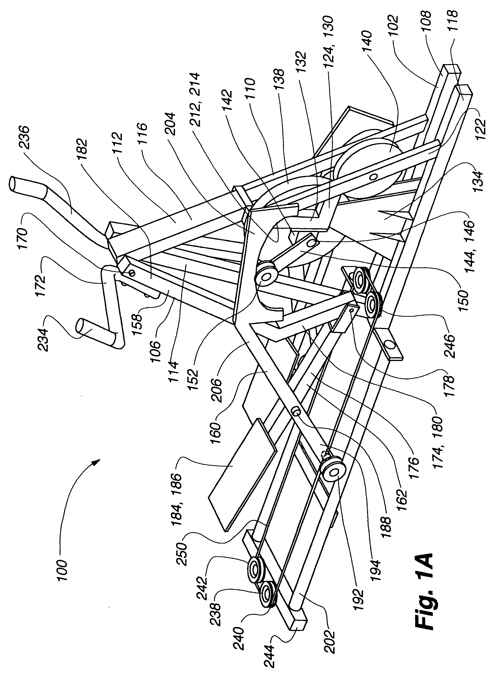
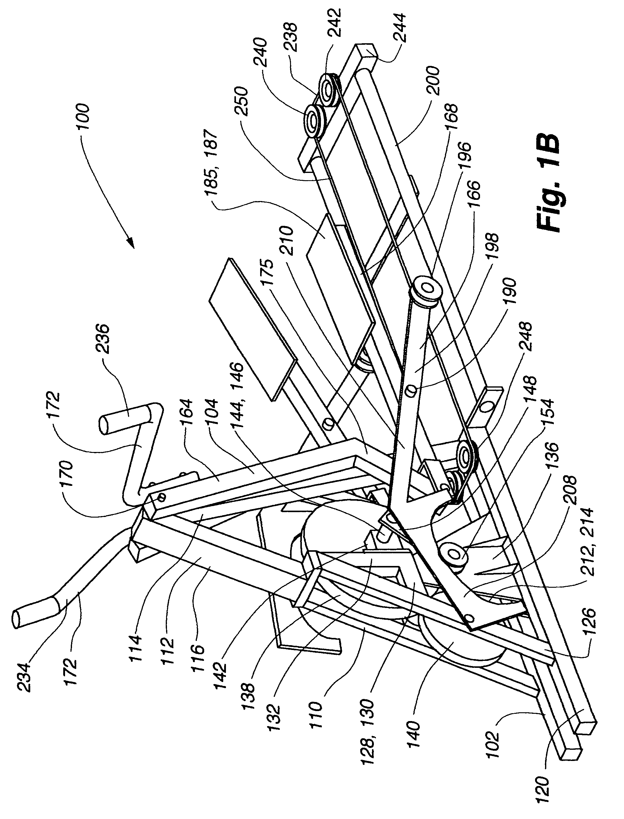
[0055]an exercise device 100 conforming to aspects of the present invention is shown in FIGS. 1A-2. The exercise device 100 includes a frame 102 having a left linkage assembly 104 and a right linkage assembly 106 connected therewith. The left linkage assembly 104 is substantially a mirror image of the right linkage assembly. The frame includes a base portion 108, a fork assembly 110, a front post 112, and a rear post 114. The combination of the fork assembly, the front post, and the rear post pivotally supports the linkage assemblies as well as supports the components that variably support the linkage assemblies.
[0056]The fork assembly 110, the front post 112, and the rear post 114 define an A-frame like support structure 116. More particularly, the fork assembly 110 and the rear post 114 are connected with the base portion 108. At the front of the device, the fork assembly 110 extends upwardly and rearwardly from the base portion 108. The front post 112 extends upwardly from the fo...
embodiment 266
[0098]A second alternative embodiment 266 of an interconnection assembly is illustrated in FIG. 9 and includes a teeter member 268, a right interconnection link 270, a left interconnection link 272, a right U-bracket 274, and a left U-bracket 276. A teeter axle 278 extends forwardly from the front post 112 and is adapted to pivotally support the teeter member 268. The left interconnection link 272 is pivotally connected with a left portion 280 of the teeter member 268 and extends downwardly therefrom to pivotally connect with the left U-bracket 276, which is rigidly connected with the left swing link 164 near the upper pivot 170. The right interconnecting link 272 is pivotally connected with a right portion 282 of the teeter member 268 and extends downwardly therefrom to pivotally connect with the right U-bracket 274, which is rigidly connected with the right swing link 158 near the upper pivot 170. When either of the swing links swing rearward, the associated U-bracket pivots downw...
second embodiment
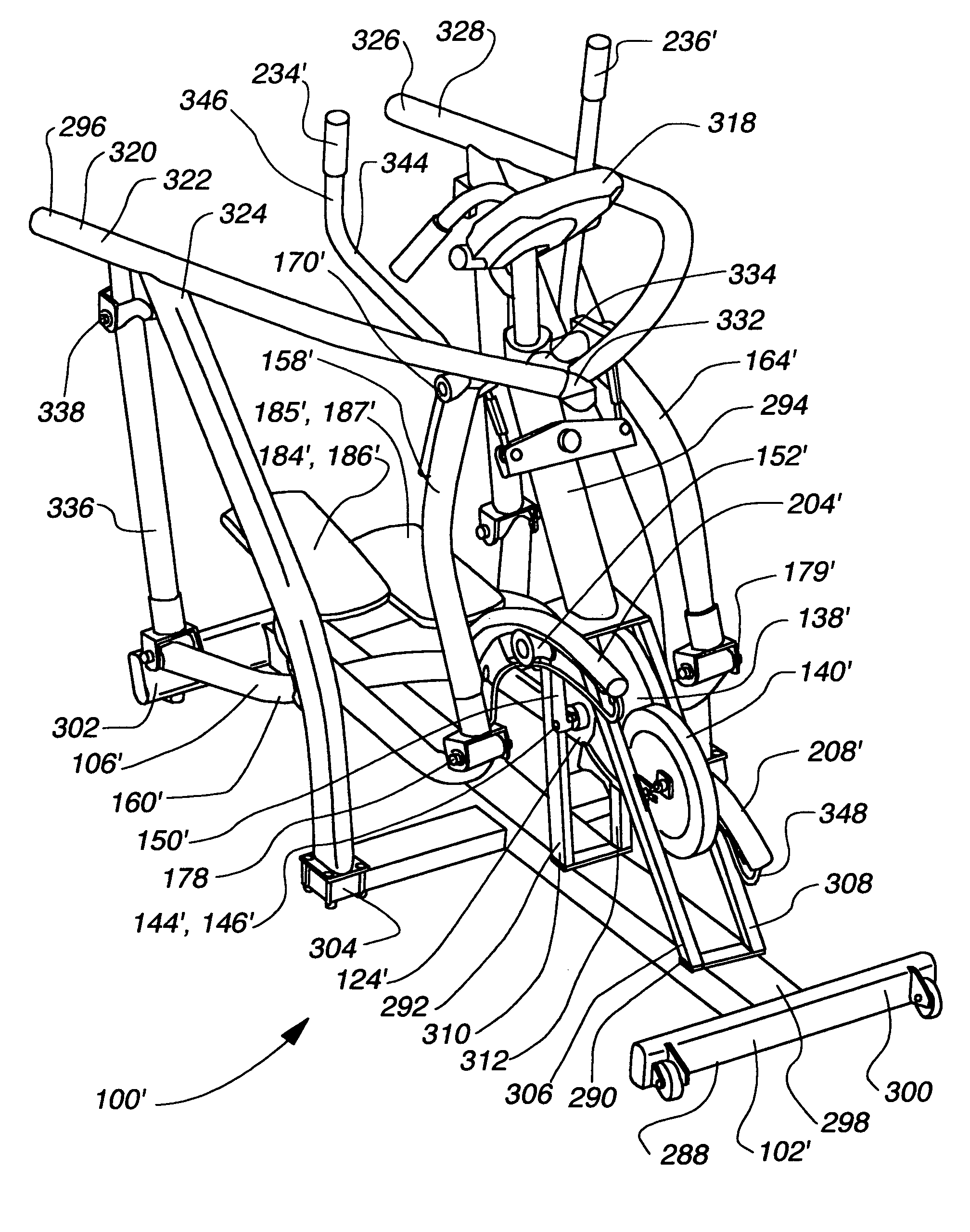
[0119]the exercise device 100′ shown in FIG. 10 also includes an interconnection assembly 266′ that acts to move the linkage assemblies in opposite directions. A detailed view of the interconnection assembly 266′ is shown in FIG. 15 and is structurally similar to the interconnection described above with reference to FIG. 9, except the teeter member is located below the upper pivot 170′. As such, the interconnection assembly 266′ includes a teeter member 268′, a right interconnection link 270′, a left interconnection link 272′, a right U-bracket 274′, and a left U-bracket 276′. A teeter axle 278′ extends forwardly from the front post 294 and is adapted to pivotally support the teeter member. The left interconnection link 272′ is pivotally connected with the left portion 280′ of the teeter member 268′ and extends upwardly therefrom to pivotally connect with the left U-bracket 276′, which is rigidly connected with the left swing link 164′ near the upper pivot 170′. The right interconne...
PUM
Abstract
The present invention provides for a variable stride exercise device having a variable size close curved striding path during use. The exercise device described and depicted herein utilizes various configurations of linkage assemblies, cam members, and other components, connected with a frame to allow a user to dynamically vary his stride path during exercise. An exercise device conforming to aspects of the present invention provides a foot path that adapts to the change in stride length rather than forcing the user into a fixed size path. A user's exertion level may have several components impacting the stride length provided by the machine, such as leg power, torso power, and (in embodiments with arm supports or exercise components) arm power. Other embodiments of the exercise device include a lockout device that selectively eliminates the variable stride features of the exercise device and allows the user to exercise in a stepping motion.
Description
CROSS-REFERENCE TO RELATED APPLICATIONS[0001]This application claims priority to U.S. Provisional Application No. 60 / 480,668, filed Jun. 23, 2003, and to U.S. Provisional Application No. 60 / 555,434, filed Mar. 22, 2004, which are hereby incorporated by reference in their entirety as though fully set forth herein.[0002]U.S. Provisional Application No. 60 / 582,232 titled, “Releasable Connection Mechanism for a Variable Stride Exercise Device,” filed Jun. 22, 2004; U.S. Provisional Application No. 60 / 582,145 titled, “Variable Stride Exercise Device,” filed Jun. 22, 2004; U.S. patent application Ser. No. 10 / 789,182, filed on Feb. 26, 2004; U.S. patent application Ser. No. 09 / 823,362, filed on Mar. 30, 2001, now U.S. Pat. No. 6,689,019; and U.S. Provisional Application No. 60 / 451,102, filed on Feb. 28, 2003 are all hereby incorporated by reference in their entirety as though fully set forth herein.BACKGROUND OF THE INVENTION[0003]a. Field of the Invention[0004]This invention relates to ex...
Claims
Application Information
Patent Timeline
Application Date:The date an application was filed.
Publication Date:The date a patent or application was officially published.
First Publication Date:The earliest publication date of a patent with the same application number.
Issue Date:Publication date of the patent grant document.
PCT Entry Date:The Entry date of PCT National Phase.
Estimated Expiry Date:The statutory expiry date of a patent right according to the Patent Law, and it is the longest term of protection that the patent right can achieve without the termination of the patent right due to other reasons(Term extension factor has been taken into account ).
Invalid Date:Actual expiry date is based on effective date or publication date of legal transaction data of invalid patent.

