
Wearable resistance device with power monitoring

Inactive Publication Date: 2017-09-28
TAU ORTHOPEDICS
View PDF15 Cites 37 Cited by
  • Summary
  • Abstract
  • Description
  • Claims
  • Application Information

AI Technical Summary

Benefits of technology

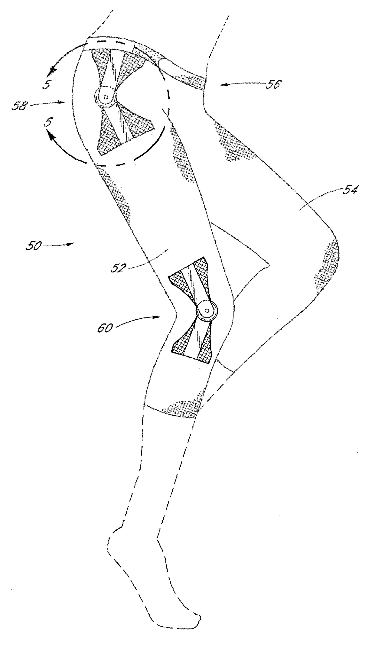
The present invention provides a wearable garment training system for monitoring stride biomechanics at a motion segment or joint such as the hip. The system includes a waist portion, a left leg portion, and a right leg portion, and biomechanics units for capturing data on flexion and extension at the hip joint. The biomechanics units each capture data on power expended by the wearer throughout a range of motion at the hip. The system may also include a processor for analyzing the data and determining power expended, stride length, stride rate, and efficiency factor. The system may also include a transmitter for transmitting the data to a remote device or a cloud-based processor. The system may be used for training and monitoring the performance of a wearer or a coach.

Problems solved by technology

Various limitations exist with the prior art exercise devices.
For example, many types of exercise equipment, such as free weights and most exercise machines, are not portable.
With respect to exercise bands and tubing, they may need to be attached to a stationary object, such as a closed door or a heavy piece of furniture, and require sufficient space.
This becomes a problem when, for example, the user wishes to perform resistance exercises in a location where such stationary objects or sufficient space are not readily found.
Resistance bands are also limited to a single resistance profile in which the amount of resistance changes as a function of angular displacement of the joint under load.
This may result in under working the muscles at the front end of a motion cycle, and over working the muscles at the back end of the cycle.
Conventional elastic devices also provide a unidirectional bias that varies in intensity throughout an angular range but not in direction.
Such devices thus cannot work both the flexor and extensor muscles of a given motion segment without adjustment, and may be uncomfortable due to the constant bias even in the absence of motion.

Method used


Image

  • Wearable resistance device with power monitoring
  • Wearable resistance device with power monitoring
  • Wearable resistance device with power monitoring

Examples


Embodiment Construction

[0077]Detailed descriptions of the preferred embodiments are provided herein. It is to be understood, however, that the present invention may be embodied in various other forms. Therefore, specific details disclosed herein are not to be interpreted as limiting, but rather as a basis for the claims and as a representative basis for teaching one skilled in the art to employ the present invention in virtually any appropriately detailed system, structure or manner.

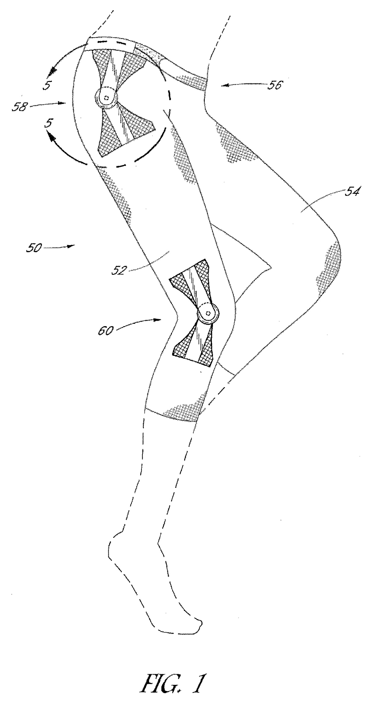
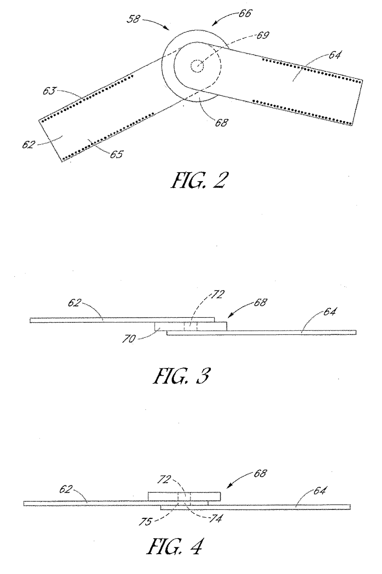
[0078]In general, the devices in accordance with the present invention are designed to provide resistance to motion between a first region and a second region of the body such as across a simple or complex joint, (e.g., hip, knee, shoulder, elbow, etc.), throughout an angular range of motion. The resistance can be either unidirectional, to isolate a single muscle or muscle group, or preferably bidirectional to exercise opposing muscle pairs or muscle groups. Optionally, the device will be user adjustable or interchangeable to ...


PUM


Abstract

Disclosed is a technical training garment configured for use with modular, interchangeable biomechanics units and or resistance modules. The garment may provide resistance to movement throughout an angular range of motion and or tracks a variety of biomechanical parameters such as stride length, stride rate, angular velocity and power expended by the wearer. The garment may be low profile, and worn by a wearer as a primary garment or beneath or over conventional clothing or athletic uniform. The device may be worn as a supplemental training and or diagnostic tool during conventional training protocols, or as a biomechanics or biometric data capture device during competition.

Description

CROSS-REFERENCE TO RELATED APPLICATIONS[0001]This application is a continuation-in-part of U.S. patent application Ser. No. 15 / 078,250, filed Mar. 23, 2016, the entirety of which is hereby expressly incorporated by reference herein.BACKGROUND OF THE INVENTION[0002]Resistance training, sometimes known as weight training or strength training, is a specialized method of conditioning designed to increase muscle strength, muscle endurance, tone and muscle power. Resistance training refers to the use of any one or a combination of training methods which may include resistance machines, dumbbells, barbells, body weight, and rubber tubing.[0003]The goal of resistance training, according to the American Sports Medicine Institute (ASMI), is to “gradually and progressively overload the musculoskeletal system so it gets stronger.” This is accomplished by exerting effort against a specific opposing force such as that generated by elastic resistance (i.e. resistance to being stretched or bent). E...

Claims


Application Information

Patent Timeline
IPC IPC(8): A63B24/00A63B71/06A41D1/08A41D31/00A41D1/00A63B21/00A63B23/04
CPCA63B24/0062A41D2400/60A63B21/4025A63B71/0619A63B23/0405A41D31/00A41D1/002A41D1/08A63B2220/34A63B2225/20A63B2220/62A63B2220/22A63B2220/54A63B2220/836A63B21/4011A41D27/205A63B21/00189A63B71/0622A63B21/0053A63B21/008A63B21/0083A63B21/0087A63B21/012A63B21/023A63B21/028A63B21/0552A63B21/159A63B23/02A63B23/0482A63B23/0494A63B23/1245A63B23/1281A63B2071/0625A63B2071/065A63B2071/0655A63B2209/02A63B2209/10A63B2220/44A63B2220/51A63B2225/50A63B2230/202A63B2230/205A63B2230/207A63B2230/42A63B2230/50A63B2230/60A63B2230/65A63B2230/75A63B21/00845A63B21/4017A63B21/4039A63B21/4047A61B5/112A41D31/18A41D31/12
Inventor MOEBIUS, JACOB A.MATSUURA, BELINKO K.MATSUURA, DAVID G.VON HOFFMANN, GERARD
Owner TAU ORTHOPEDICS
Learn More