
Coffee maker

a coffee maker and coffee technology, applied in beverage vessels, household appliances, kitchen equipment, etc., can solve the problems of generating large noise, complicated clutch design, and affecting the quality of coffee,

Inactive Publication Date: 2008-12-30
MAK CHI KIN JOHN
View PDF19 Cites 64 Cited by
  • Summary
  • Abstract
  • Description
  • Claims
  • Application Information

AI Technical Summary

Benefits of technology

The solution provides a hygienic, quiet, and efficient coffee-making process with improved filtration and consistent flavor control, ensuring even water distribution and extraction of coffee flavors through controlled centrifugal forces and rotational speeds.

Problems solved by technology

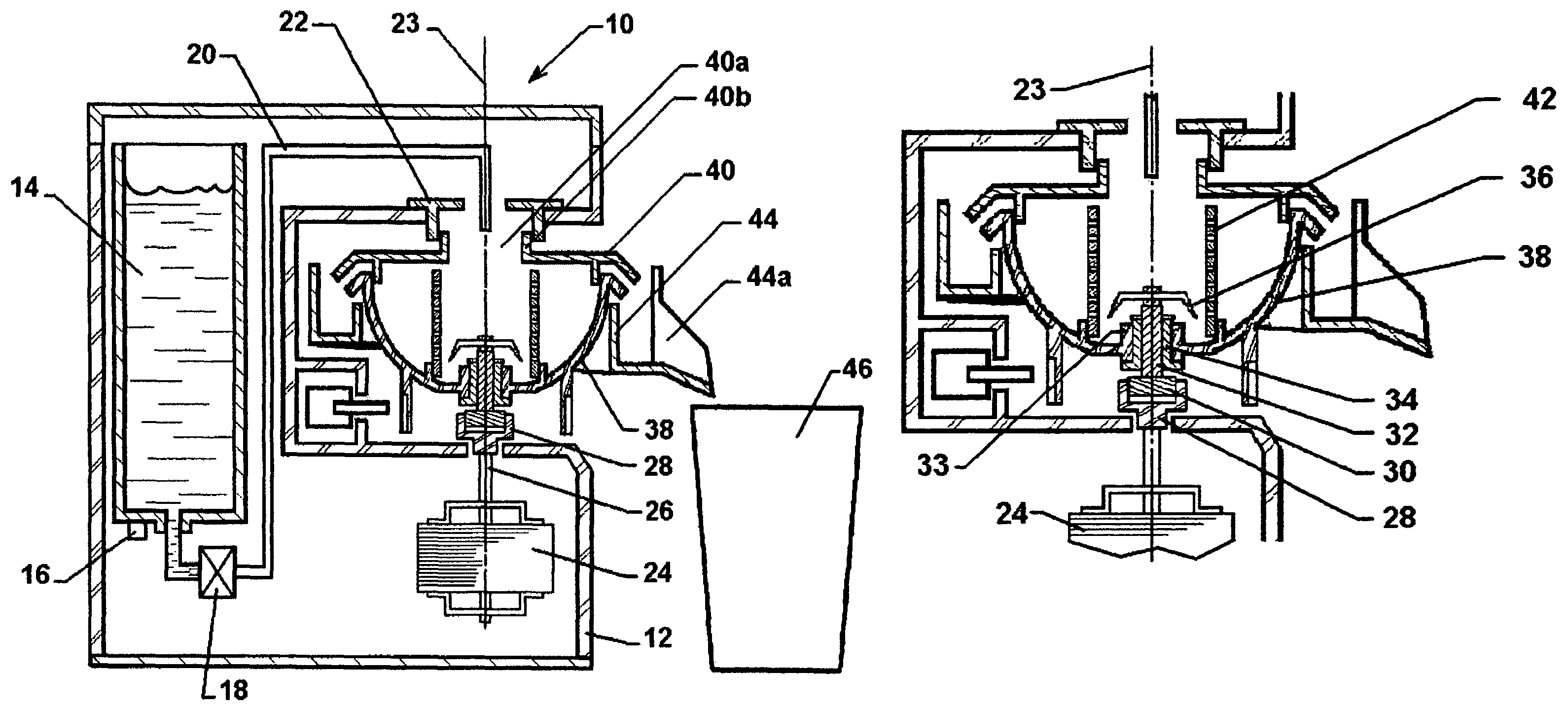
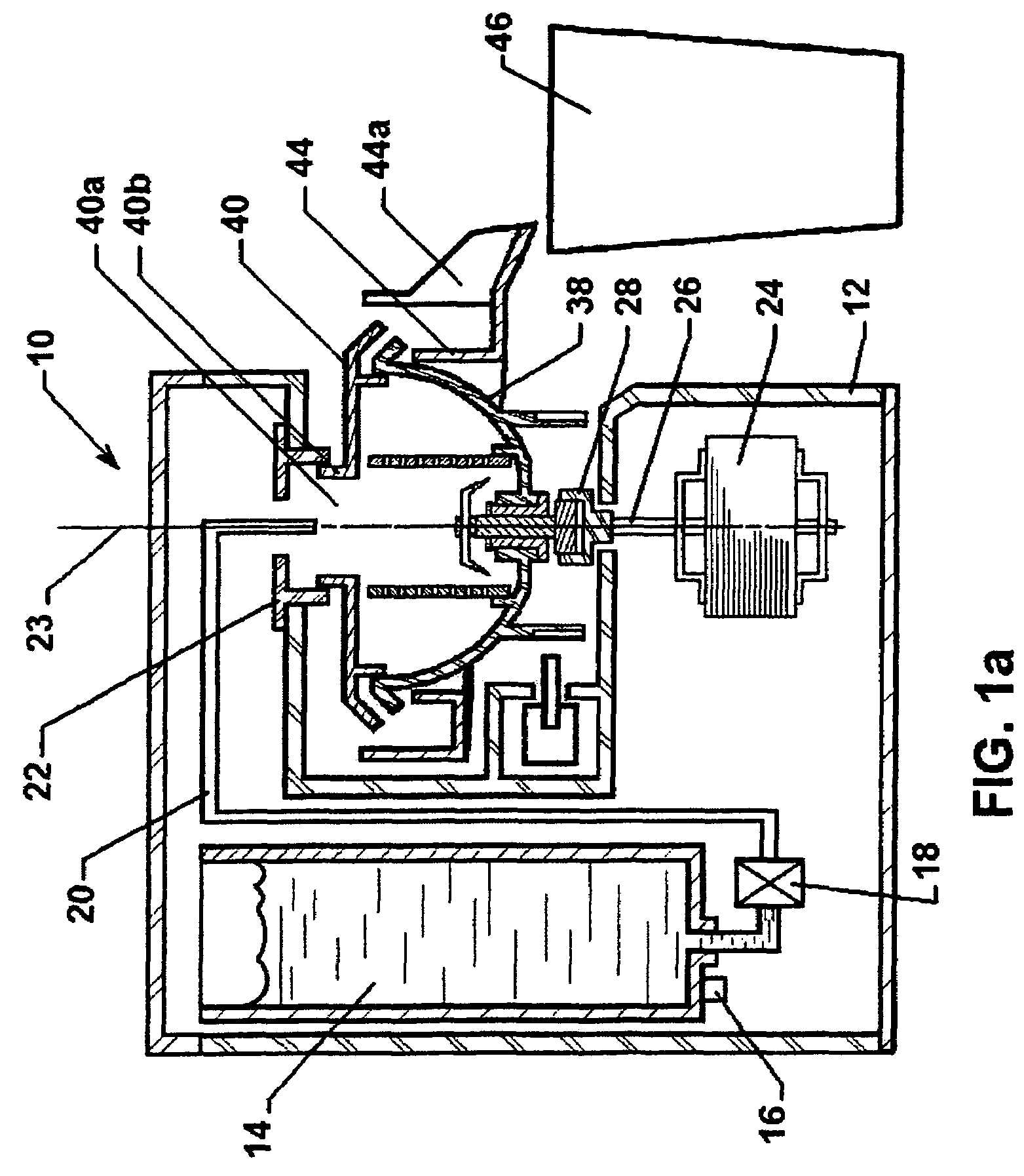
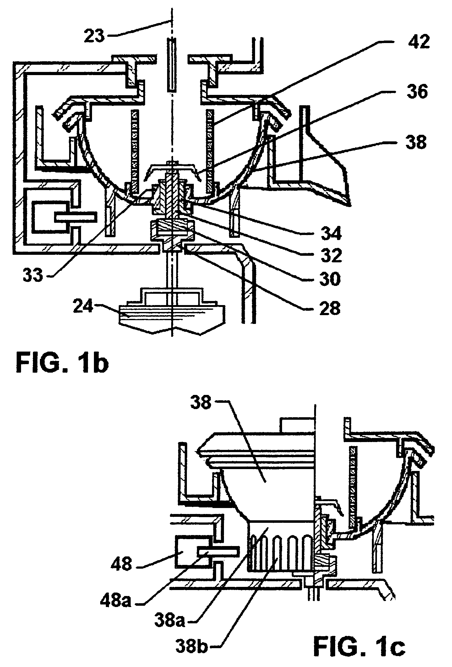
However, the channel connecting the two chambers is hidden and is not accessible to be cleaned, which creates a hygiene issue.
The clutch design is complicated and ends up the accumulated mechanical tolerance which creates misalignment between the brewing basket, chopping blade and motor.
As such, when the brewing basket is rotated at a high speed, an intense oscillation and a big noise will be generated.
However, the timing to wet all coffee powder varies with many uncontrollable factors, such as the amount of powder, size of powder, nature of the coffee.
If the timing is too short, a mixture of un-wetted and wetted coffee powder lumps is generated, which creates an uneven load distribution.
If the timing is too long, the hot water stays with the coffee powder for long time, which makes the coffee bitter.
The filtration area is small and is not effective for filtering.
Consequently, there is a potential problem of overflow.

Method used


Image

  • Coffee maker
  • Coffee maker
  • Coffee maker

Examples


Embodiment Construction

[0034]Reference will now be made in detail to exemplary embodiments, examples of which are also provided in the following description. It will be apparent to those skilled in the relevant art that some features that are not particularly important to an understanding of the invention may not be shown for the sake of clarity.

[0035]Furthermore, it should be understood that the invention is not limited to the precise embodiments described below and that various changes and modifications thereof may be effected by one skilled in the art without departing from the spirit or scope of the invention. For example, elements and / or features of different illustrative embodiments may be combined with each other and / or substituted for each other within the scope of this disclosure and appended claims.

[0036]In addition, improvements and modifications which may become apparent to persons of ordinary skill in the art after reading this disclosure, the drawings, and the appended claims are deemed with...


PUM


Abstract

A coffee maker with combined milling stage and brewing stage is provided. The coffee maker includes a shaft, a brewing basket, a chopping blade and a locking mechanism. The shaft includes a longitudinal axis and is capable of being rotated about the axis. The brewing basket is adapted to receive coffee beans and hot water. The brewing basket includes a sleeve. A portion of the shaft is movably fitted within the sleeve. The brewing basket is capable of being rotated about the axis. The chopping blade is attached to an end of the shaft and positioned within the brewing basket. The locking mechanism is adapted to lock the brewing basket and unlock the brewing basket. When the brewing basket is locked, rotation of the shaft drives the chopping blade to rotate about the axis to mill the coffee beans to produce milled coffee powder. When the brewing basket is unlocked, rotation of the shaft generates frictional forces on the brewing basket to drive the brewing basket to rotate to generate centrifugal forces, causing the hot water to penetrate the milled coffee powder to produce brewed coffee.

Description

RELATED APPLICATION[0001]This application claims the benefit of U.S. Provisional Patent Application Ser. No. 60 / 724,872, filed Oct. 11, 2005, which is incorporated by reference herein in its entirety.FIELD OF THE INVENTION[0002]The present invention relates to a coffee maker and, in particular, to a centrifugal type coffee maker combining both coffee milling and brewing in one chamber.BACKGROUND OF THE INVENTION[0003]In the market, many coffee makers claiming to have both milling and brewing functions simply pack a motorized coffee mill and a regular coffee maker together under one roof. Coffee beans are being milled and brewed in separated chambers. Some coffee makers do provide a built-in channel to transfer milled coffee powder from the milling chamber to the brewing chamber. However, the channel connecting the two chambers is hidden and is not accessible to be cleaned, which creates a hygiene issue.[0004]The coffee maker of the type described above is disclosed in U.S. Pat. No. ...

Claims


Application Information

Patent Timeline
Patent Type & Authority Patents(United States)
IPC IPC(8): A47J31/00
CPCA47J31/22A47J31/42
Inventor LI, ZHIPING
Owner MAK CHI KIN JOHN
Learn More