Locking pliers

a technology of locking mechanism and pliers, which is applied in the field of locking pliers, can solve the problems of increasing the cost and complexity of wrench manufacturing, and changing the geometry of the locking mechanism

Inactive Publication Date: 2009-01-06
BLACK & DECKER INC
View PDF14 Cites 28 Cited by
  • Summary
  • Abstract
  • Description
  • Claims
  • Application Information

AI Technical Summary

Problems solved by technology

One problem with such an arrangement is that because the release lever is disposed between the handle and a link of the locking mechanism, the dimensions and configuration of the release lever and its location within the handle changes the geometry of the locking mechanism.
The controls required during manufacture and assembly of these components increase the cost and complexity of manufacturing of the wrench.

Method used


Image

  • Locking pliers
  • Locking pliers
  • Locking pliers

Examples


Embodiment Construction

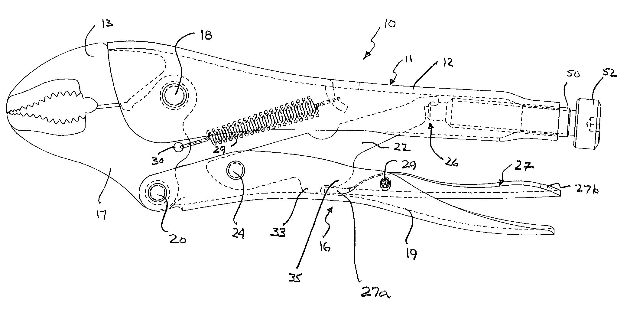
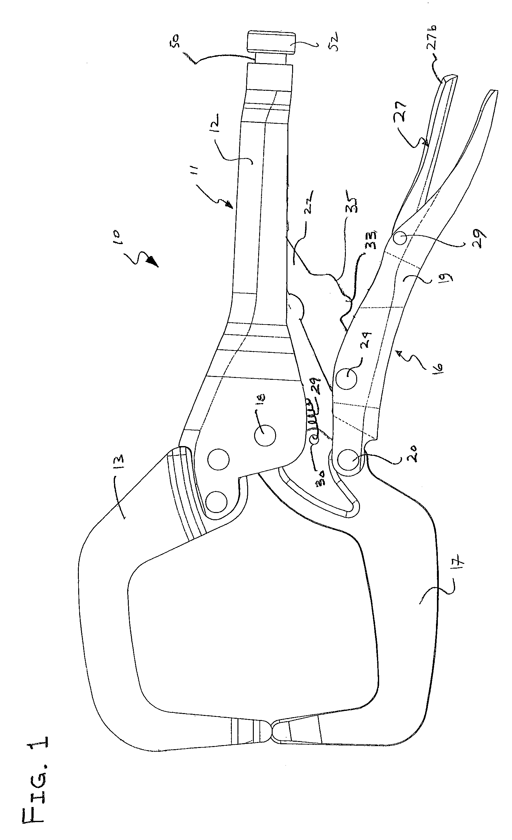
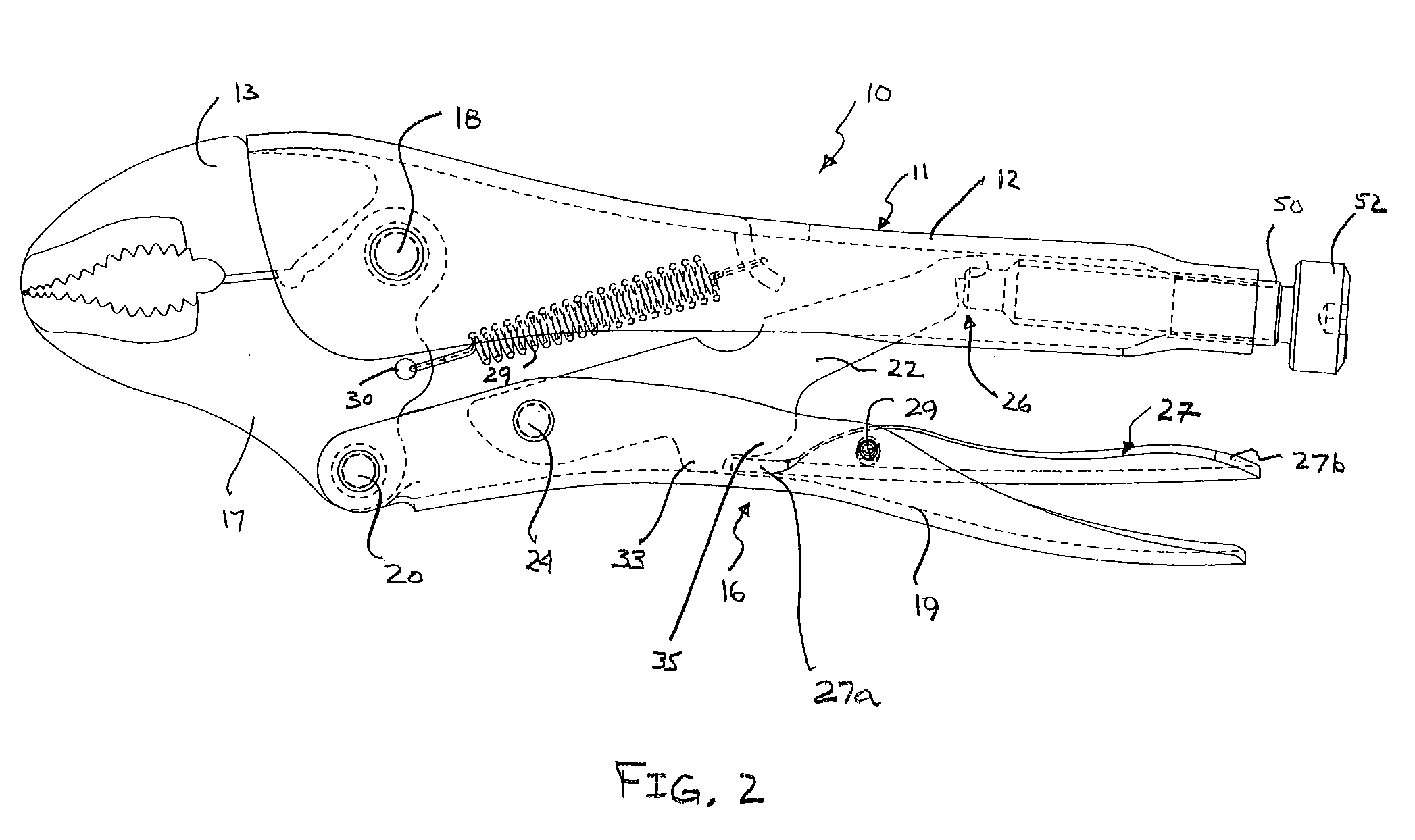
[0015]The release mechanism of the invention is intended to be used with any locking pliers that use a linkage to lock the jaws in position and apply the clamping force by the jaws to a work piece including simple toggle-locking mechanisms, compound toggle-locking mechanisms and self-adjusting locking pliers. Various configurations of the toggle locking mechanisms, jaws and handles may be used in conjunction with the release mechanism of the invention. The jaws may be shaped to function as long nose pliers, pliers with curved jaws, serrated jaws, C-clamps, C-clamps with swivel pads, hole punches, or any other kind of hand tool where the toggle-locking action is useful. The embodiment of the pliers shown in FIG. 1 shows clamp jaws and the embodiment of the pliers shown in FIGS. 2 through 4 show traditional pliers jaws.

[0016]For purposes of explaining the construction and operation of the adjustment mechanism of the invention, one such locking pliers 10 will be described in detail wit...


PUM


Abstract

The locking pliers comprises a first handle connected to a first jaw. A second handle and second jaw are pivotably connected to the first handle and first jaw such that movement of the first handle relative to the second handle causes the jaws to open and close. A mechanism is provided to lock the jaws relative to one another and apply a clamping or gripping force on a workpiece positioned between the jaws. A release mechanism is provided to unlock the pliers that is independent of the locking operation.

Description

BACKGROUND[0001]This invention relates generally to locking pliers and, more particularly, to an improved release mechanism for such pliers.[0002]Pliers-type hand tools with toggle-locking mechanisms are generally known as locking pliers. These pliers usually comprise a fixed handle having a fixed jaw on one end thereof. A movable jaw and a movable handle are pivotal relative to the fixed handle to open and close the jaws. To operate the pliers the movable handle is closed relative to the fixed handle to close the jaws and seize a workpiece firmly therebetween. The handles are then tightly compressed such that the toggle mechanism locks the pliers onto the workpiece. The pliers will remain firmly locked in place without the continuous application of force by the user.[0003]The pliers may comprise a relatively simple toggle-locking mechanism where a single link has one end pivotably connected to the movable jaw and the opposite end adjustably and pivotably received in the movable han...

Claims


Application Information

Patent Timeline
Patent Type & Authority Patents(United States)
IPC IPC(8): B25B7/12
CPCB25B7/123
Inventor ENGVALL, DAVID P.CHERVENAK, THOMAS M.
Owner BLACK & DECKER INC
Why Eureka
Try Eureka