Reactive deadlock management in storage area networks
What is Al technical title?
Al technical title is built by PatSnap Al team. It summarizes the technical point description of the patent document.
a deadlock management and storage area technology, applied in the field of storage area networks, can solve the problems of increasing the difficulty of managing raw data storage, the difficulty of transferring raw data, and the inability of physical targets to handle a limited number of transfer requests, so as to achieve the maximum number of requests, the maximum count of requests, and the effect of queue depth
Active Publication Date: 2009-01-27
EMC IP HLDG CO LLC
View PDF7 Cites 33 Cited by
Summary
Abstract
Description
Claims
Application Information
AI Technical Summary
This helps you quickly interpret patents by identifying the three key elements:
Problems solved by technology
Method used
Benefits of technology
Problems solved by technology
More particularly, the management of raw data storage is becoming more cumbersome and difficult as more companies and individuals are faced with larger and larger amounts of data that must be effectively, efficiently, and reliably maintained.
Nevertheless, the space may actually be divided over multiple physical storage devices and even be fragmented within single storage devices.
Typically, physical targets are only able to handle a limited number of transfer requests at a given time.
Unbuffered data transfer between servers and targets, however, can present further obstacles to the switches routing such data.
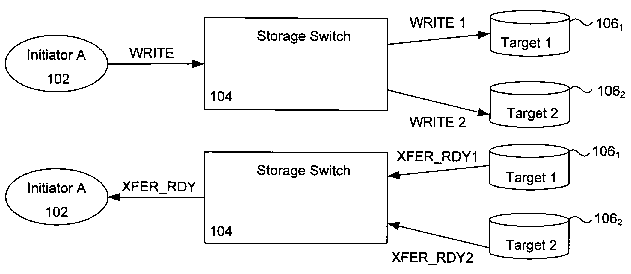
If not properly managed, a network or portion thereof can become deadlocked while attempting to write the data.
Because of each target's limited ability to issue transfer ready signals, the switch and targets can become deadlocked waiting for either transfer ready resources or data packets.
Additionally, the switch can not provide a transfer ready signal for the write B command to the initiator until it receives a transfer ready signal for the write B command.
Method used
Image
Click on the blue label to locate the original text in one second.
Reading with bidirectional positioning of images and text.
Examples
Embodiment Construction
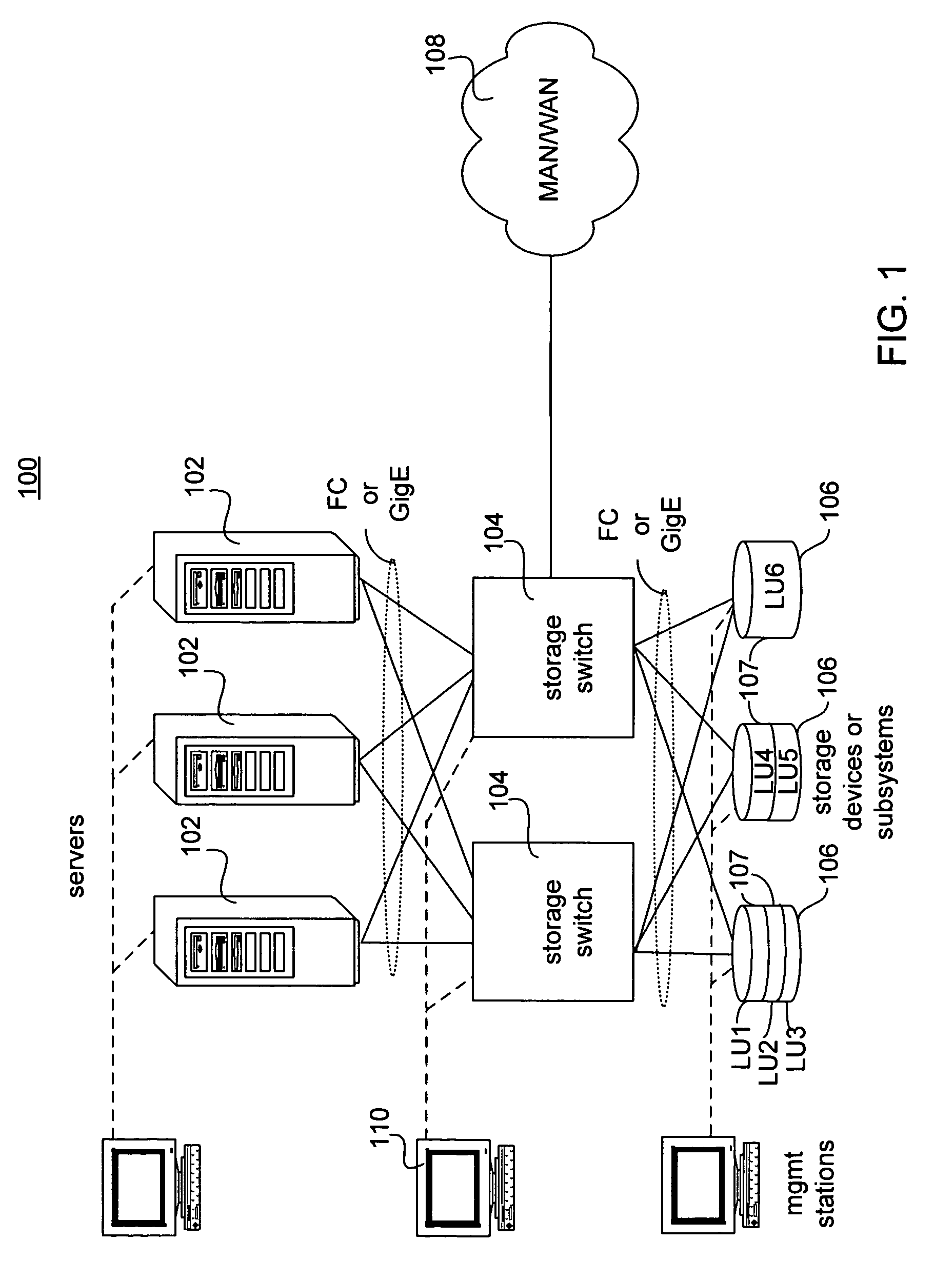
[0049]An exemplary system 100 including a storage switch in accordance with one embodiment is illustrated in FIG. 1. System 100 can include a plurality of initiating devices such as servers 102. It will be appreciated that more or fewer servers can be used and that embodiments can include any suitable physical initiator in addition to or in place of servers 102. Although not shown, the servers could also be coupled to a LAN. As shown, each server 102 is connected to a storage switch 104. In other embodiments, however, each server 102 may be connected to fewer than all of the storage switches 104 present. The connections formed between the servers and switches can utilize any protocol, although in one embodiment the connections are Fibre Channel or Gigabit Ethernet (carrying packets in accordance with the iSCSI protocol). Other embodiments may use the Infiniband protocol, defined by Intel Inc., or other protocols or connections.
[0050]In some embodiments, one or more switches 104 are ...
PUM
Abstract
Systems and methods in accordance with various embodiments can detect and alleviate potential or actual deadlock of a storage switch or storage area network when attempting to write data to a mirrored virtual target. In accordance with one embodiment, a timer is started when a storage switch routes a write command to the physical targets corresponding to a virtual target of the write command. If each physical target does not return a transfer ready resource within a predetermined timeout period, the switch determines that a potential or actual deadlock has occurred. An abort command is sent to each of the physical devices. The abort command can clear the command from the targets and also free any allocated transfer ready resources. After receiving an acceptance response from each physical target, the state of the write command at the switch can be cleared. The write command can then be re-issued to the physical devices. In one embodiment, a queue depth for the virtual target can be lowered after failing to receive transfer ready resources from each target. By decreasing the queue depth, the maximum number of commands the switch will process for a virtual target is decreased to decrease the probability of future deadlock. In one embodiment, the queue depth is increased after no deadlock is detected for a period of time.
Description
CROSS-REFERENCE TO RELATED APPLICATIONS[0001]The following applications are cross-referenced and incorporated by reference herein in their entirety:[0002]U.S. patent application Ser. No. 10 / 833,438, entitled PROACTIVE TRANSFER READY RESOURCE MANAGEMENT IN STORAGE AREA NETWORKS, filed Apr. 28, 2004;[0003]U.S. patent application Ser. No. 10 / 051,321, entitled STORAGE SWITCH FOR STORAGE AREA NETWORK, filed Jan. 18, 2002;[0004]U.S. patent application Ser. No. 10 / 051,415, entitled PROTOCOL TRANSLATION IN A STORAGE SYSTEM, filed Jan. 18, 2002;[0005]U.S. patent application Ser. No. 10 / 051,164, entitled SERVERLESS STORAGE DEVICES, filed Jan. 18, 2002, now U.S. Pat. No. 7,185,062, issued Feb. 27, 2007;[0006]U.S. patent application Ser. No. 10 / 051,093, entitled PACKET CLASSIFICATION IN A STORAGE SYSTEM, filed Jan. 18, 2002;[0007]U.S. patent application Ser. No. 10 / 051,396, entitled VIRTUALIZATION IN A STORAGE SYSTEM, filed Jan. 18, 2002;[0008]U.S. patent application Ser. No. 10 / 051,339, entitl...
Claims
Application Information
Patent Timeline
Application Date:The date an application was filed.
Publication Date:The date a patent or application was officially published.
First Publication Date:The earliest publication date of a patent with the same application number.
Issue Date:Publication date of the patent grant document.
PCT Entry Date:The Entry date of PCT National Phase.
Estimated Expiry Date:The statutory expiry date of a patent right according to the Patent Law, and it is the longest term of protection that the patent right can achieve without the termination of the patent right due to other reasons(Term extension factor has been taken into account ).
Invalid Date:Actual expiry date is based on effective date or publication date of legal transaction data of invalid patent.
