Colour calibration of emissive display devices

a technology of emissive display and colour calibration, which is applied in the direction of static indicating devices, cathode-ray tube indicators, instruments, etc., can solve the problems of sacrificing the potential colour gamut of a given display, difficult to manufacture single units for large fixed-format displays, etc., and achieve the effect of expanding the potential colour gamu

Active Publication Date: 2005-08-11
BARCO NV
View PDF6 Cites 34 Cited by
  • Summary
  • Abstract
  • Description
  • Claims
  • Application Information

AI Technical Summary

Benefits of technology

[0011] It is an object of the present invention to extend the potential colour gamut which can be addressed by substantially all pixels of a fixe

Problems solved by technology

Making very large fixed format displays as single units manufactured on a single substrate is difficult.
As the human eye is very sensitive to colour differences, colour variations between the

Method used


Image

  • Colour calibration of emissive display devices
  • Colour calibration of emissive display devices
  • Colour calibration of emissive display devices

Examples


Embodiment Construction

[0039] The present invention will be described with respect to particular embodiments and with reference to certain drawings but the invention is not limited thereto but only by the claims. The drawings described are only schematic and are non-limiting. In the drawings, the size of some of the elements may be exaggerated and not drawn on scale for illustrative purposes.

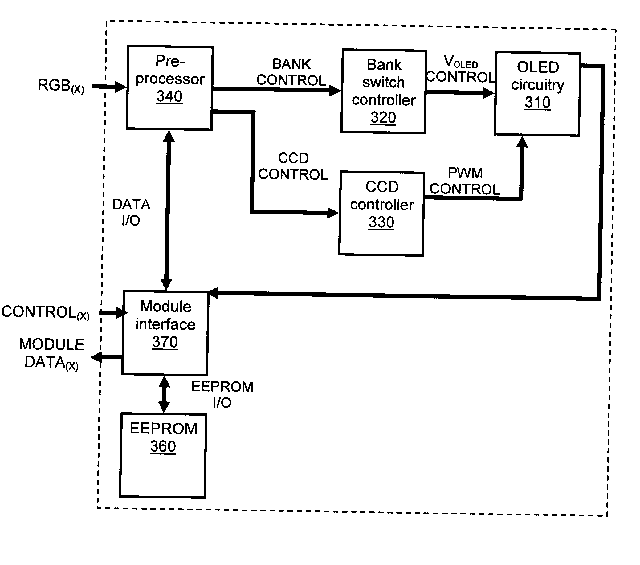
[0040] The present invention will be described with reference to an OLED display, especially a tiled OLED display, but the present invention is not limited to tiled OLED displays but may be used with any tiled or monolithic emissive display.

[0041] In the following an emissive pixel structure refers to an emissive, fixed format pixel which may comprise a number of pixel elements, e.g. red, green and blue pixel elements. Each pixel element or colour element may itself be made up of one or more sub-elements. Hence, a pixel structure may comprise sub-pixel elements. A pixel structure may be monochromatic or coloured. Fu...


PUM


Abstract

A calibration method for calibrating a fixed format emissive display device having a plurality of pixels is described In the display each pixel comprises at least three sub-pixels for emitting light of different real primary colours. The method comprises determining, for each real primary colour separately, a virtual target primary colour which can be reached by at least 80% of the pixels of the display, determining a colour gamut defined by the determined virtual target primary colours, and adjusting the drive currents to the sub-pixels to achieve a colour inside the determined colour gamut. A display having an extended range of colours is described, i.e. a gamut of colours that is more than the gamut provided by an n virtual primary colour based electronic multicolour display, as measured on a chromaticity diagram, for example. A color and/or brightness uniform image can be produced with this fixed format emissive display device.

Description

TECHNICAL FIELD OF THE INVENTION [0001] The present invention relates to emissive displays, especially fixed format emissive displays such as flat panel displays, and more particularly to a method and device for colour calibration of such displays. BACKGROUND OF THE INVENTION [0002] Electronic displays can use transmissive or emissive materials to generate pictures or light. Emissive materials are usually phosphorescent or electroluminescent materials. Examples are inorganic electroluminescent materials such as applied in thin film and thick film electroluminescent displays (EL-displays, for example thin film TFEL displays as manufactured by Sharp, Planar, LiteArray or iFire / Westaim). Another group is organic electroluminescent materials (such as Organic Light Emitting Diode (OLED) material) deposited in layers comprising small molecule or polymer technology or phosphorescent OLED, where the electroluminescent materials are doped with a phosphorescent material. Yet another group of ...

Claims


Application Information

Patent Timeline
IPC IPC(8): G09G3/20G09G3/22G09G3/32G09G5/02
CPCG09G3/2077G09G3/22G09G3/32G09G5/02G09G2320/043G09G2320/0233G09G2320/0276G09G2320/0285G09G2320/04G09G2300/026
Inventor BOUWENS, LUCDEDENE, NELETHIELEMANS, ROBBIE
Owner BARCO NV
Why Eureka
Try Eureka