Liquid crystal display with the red, green, blue, and yellow sub-pixels surrounding the white sub-pixel

a liquid crystal display and sub-pixel technology, applied in static indicating devices, instruments, optics, etc., can solve the problems of large dimension and high power consumption, easy deterioration of refractive birefringence properties, and inability to have colored filters in the sub-pixels, so as to achieve the effect of enlarge the color gamu

Inactive Publication Date: 2007-07-24
LG DISPLAY CO LTD
View PDF3 Cites 43 Cited by
  • Summary
  • Abstract
  • Description
  • Claims
  • Application Information

AI Technical Summary

Benefits of technology

[0024]Another advantage of the present invention is to provide a liquid crystal display device that enlarges a color gamut.

Problems solved by technology

A cathode ray tube (CRT) has been mainly used as displays for televisions and desktop computer monitors, but the CRT has disadvantages of heavy weight, large dimension and high power consumption.
Especially, such residual images occur at the time of applying DC voltage between the common and pixel electrodes because the liquid crystal has refractive birefringence property and is easily deteriorated by the DC voltage.
Meanwhile, the white (W) sub-pixels may not have any colored filters because a light source employed in the LCD device usually emits white-colored light.
Among the above-mentioned color filter arrangements, the stripe type, mosaic type, triangle type and square type arrangements provide relatively low brightness, and have the disadvantages of the invariable and stationary aperture and contrast ratios.
Furthermore, although the high brightness and improved aperture and contrast ratios are obtained, the LCD device having the quad type arrangement needs a complicated circuit and requires the high costs of production because an additional data signal is required for the white (W) sub-pixel.

Method used


Image

  • Liquid crystal display with the red, green, blue, and yellow sub-pixels surrounding the white sub-pixel
  • Liquid crystal display with the red, green, blue, and yellow sub-pixels surrounding the white sub-pixel
  • Liquid crystal display with the red, green, blue, and yellow sub-pixels surrounding the white sub-pixel

Examples


Embodiment Construction

[0042]Reference will now be made in detail to the illustrated embodiments of the present invention, examples of which are illustrated in the accompanying drawings. Wherever possible, the same reference number will be used throughout the drawings to refer to the same or like parts.

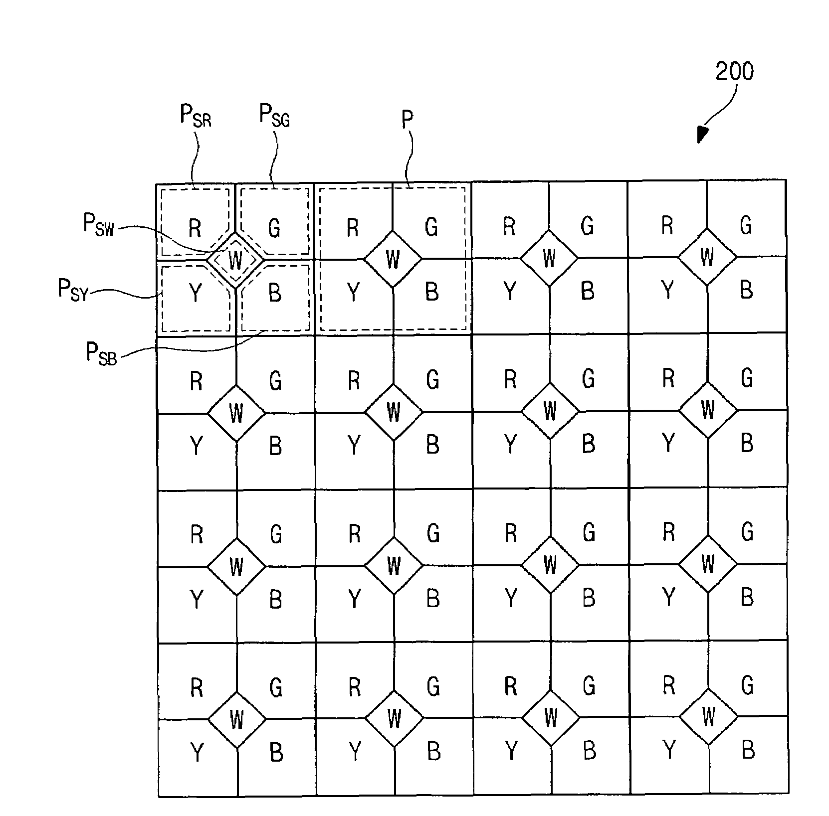
[0043]FIG. 8 is a plan view illustrating a sub-pixel arrangement of a liquid crystal display device according to the present invention. Gate lines, data lines and thin film transistors are omitted in the sub-pixels of FIG. 8 to simply explanation.

[0044]In FIG. 8, a liquid crystal display (LCD) device 200 includes a plurality of pixels P each displaying a certain color. Each of the pixels P includes red (R), green (G), blue (B), yellow (Y) and white (W) sub-pixels PSR, PSG, PSB, PSY and PSW each representing red, green, blue, yellow and white colors. Each of the R, G, B and Y sub-pixels PSR, PSG, PSB, and PSY is substantially shaped like a rectangle and has a corner-cut side at one corner thereof. The R, G, ...


PUM

PropertyMeasurementUnit
voltageaaaaaaaaaa
voltagesaaaaaaaaaa
polaritiesaaaaaaaaaa

Abstract

A LCD device includes a first substrate including a plurality of pixels each having a white (W) sub-pixel and red (R), green (G), blue (B) and yellow (Y) sub-pixels surrounding the W sub-pixel; thin film transistors each connected to gate and data lines over the first substrate; first to fourth pixel electrodes connected to each of the thin film transistors and disposed to correspond to one of the R, G, B and Y sub-pixels; a color filter layer including red (R), green (G), blue (B) and yellow (Y) color filters on a second substrate, each of the R, G, B and Y color filters corresponding to one of the R, G, B and Y sub-pixels; a common electrode on the color filter layer; and a liquid crystal layer interposed between the color filter layer and the first to fourth pixel electrodes.

Description

[0001]This application claims the benefit of Korean Patent Application No. P2003-0098643 filed on Dec. 29, 2003, which is hereby incorporated by reference for all purposes as if fully set forth herein.BACKGROUND OF THE INVENTION[0002]1. Field of the Invention[0003]The present invention relates to a liquid crystal display (LCD) device, and more particularly, to a LCD device having a dynamic aperture ratio control system for controlling aperture ratio and brightness.[0004]2. Discussion of the Related Art[0005]A cathode ray tube (CRT) has been mainly used as displays for televisions and desktop computer monitors, but the CRT has disadvantages of heavy weight, large dimension and high power consumption. Therefore, flat panel display (FPD) devices have been demanded to substitute the CRT. For example, liquid crystal display (LCD) devices and electroluminescent display (ELD) devices have been researched and developed. Particularly, the LCD devices make use of optical anisotropy and polari...

Claims


Application Information

Patent Timeline
Patent Type & Authority Patents(United States)
IPC IPC(8): G02F1/1335G02F1/133G02F1/1343G02F1/136G02F1/1368H01L29/786
CPCG02F1/133514G02F1/134363G02F2201/52G02F2001/134345G02F1/134345G02F1/1343
Inventor YUN, JAE-KYEONG
Owner LG DISPLAY CO LTD
Why Eureka
Try Eureka