
Variable focus imaging lens assembly for an imaging-based bar code reader

a bar code reader and variable focus technology, applied in instruments, sensing record carriers, sensing by electromagnetic radiation, etc., can solve the problems of system perception as sluggish, poor resolution of imaged target bar codes, and difficult and costly implementation

Active Publication Date: 2008-12-04
SYMBOL TECH LLC
View PDF10 Cites 34 Cited by
  • Summary
  • Abstract
  • Description
  • Claims
  • Application Information

AI Technical Summary

Benefits of technology

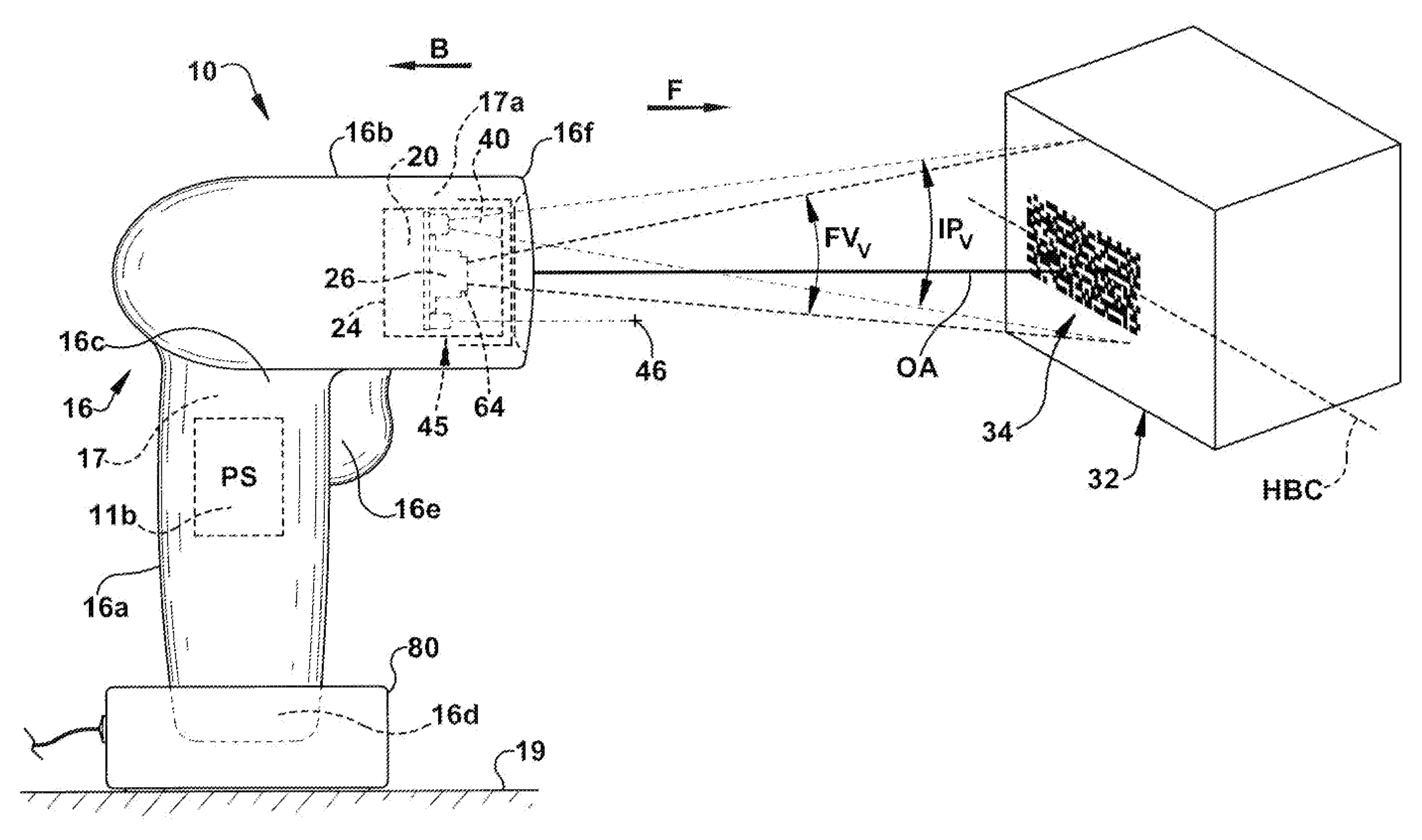
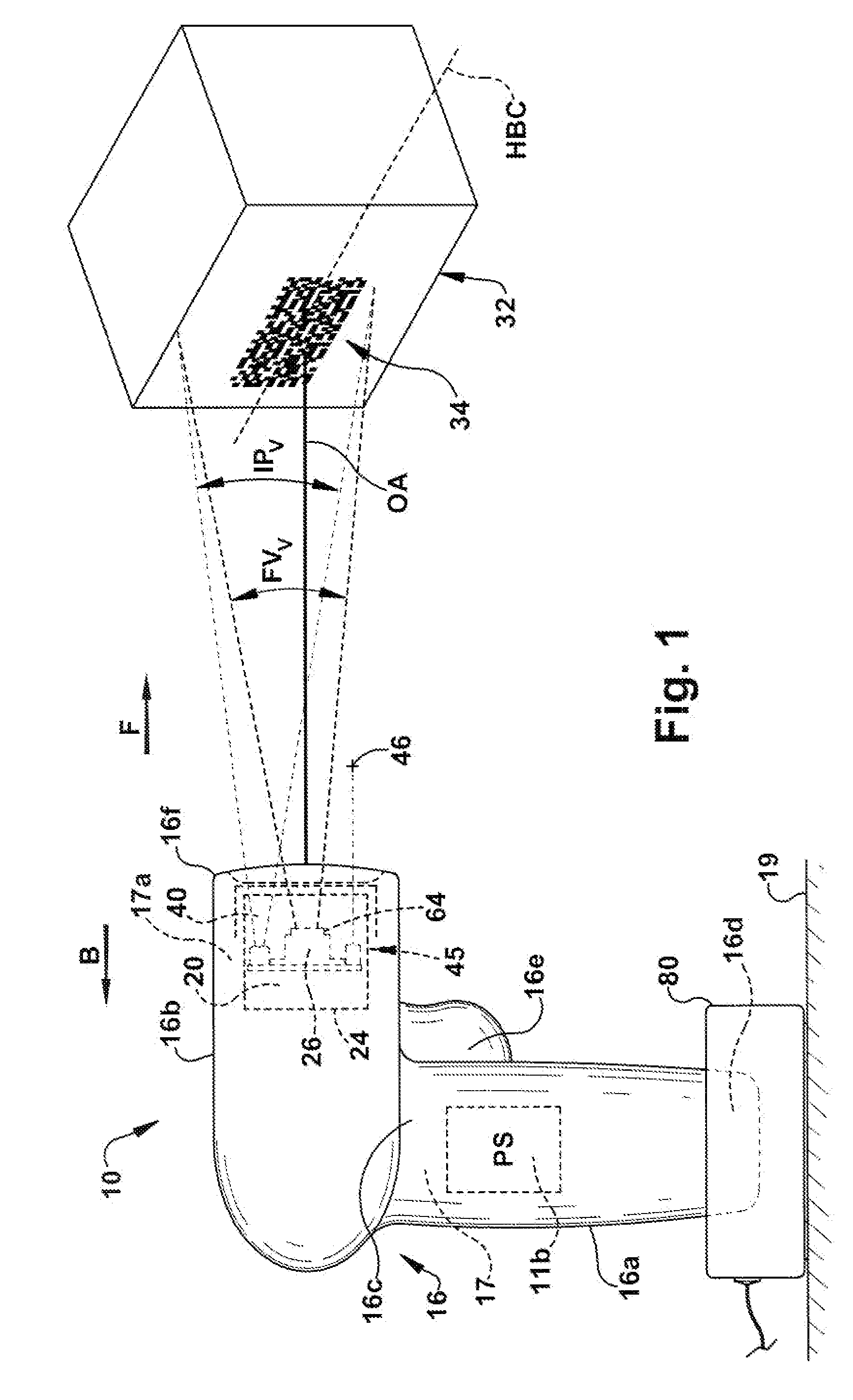
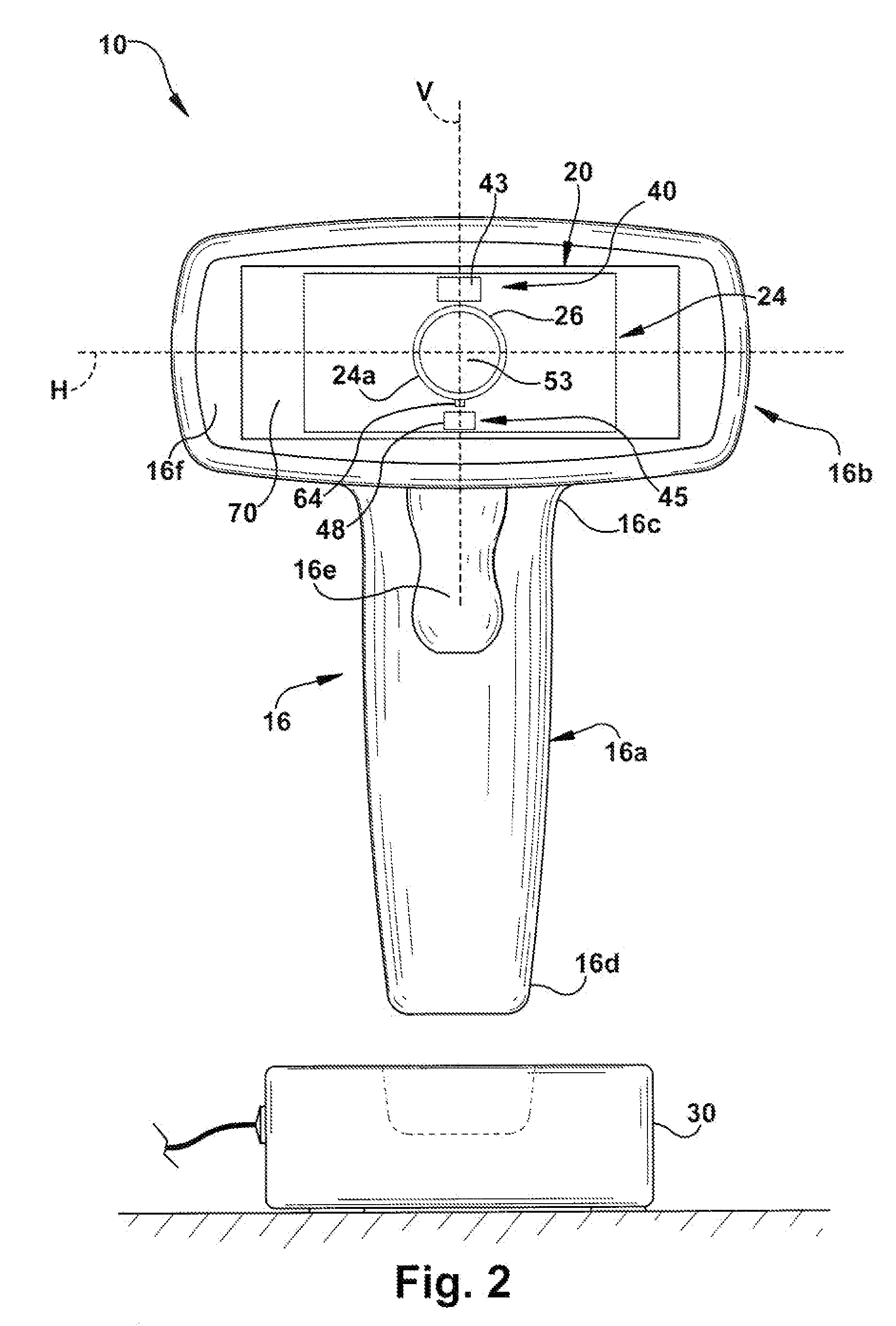
The present invention is about a variable focus imaging lens assembly for an imaging-based bar code reader. The lens assembly includes a movable lens that can be focused onto the field of view of the reader. The lens assembly is driven by a drive mechanism and a focusing system that establishes a reference point for the lens. A projection assembly is also included that projects a virtual image of a light source to a predetermined position within the field of view. The lens assembly and the projection assembly work together to determine the acceptable in-focus resolution of the virtual image. The invention allows for improved focus and better image quality in the bar code reader.

Problems solved by technology

At the near and far limits of the working range (WR), there is a problem with blurriness, that is, poor resolution of the imaged target bar code.
If it turns out that the first decodable image frame is somewhere around the middle of the moving lens path of travel, it is easy to see that this type of autofocusing system would, on the average, be slow in acquiring a decodable image of the target object, thus, causing the system to be perceived as sluggish.
These types of systemic changes in a previously established lens reference position is called a bias error and is of a much more serious nature than differential errors, that is, errors that result in inaccuracies of from moving the lens one position to another along its path of travel.
Additionally, variable focus lens assemblies typically do not provide a mechanical stop that could be used as a moving lens reference point because such a mechanical stop along the moving lens path of travel may not be possible or, if possible, may be difficult and costly to implement.
Further, while such mechanical stops may provide accurate positions for starting and ending positions along the moving lens path of travel, such mechanical end stops do not provide any feedback to locate the lens in an intermediate position.

Method used


Image

  • Variable focus imaging lens assembly for an imaging-based bar code reader
  • Variable focus imaging lens assembly for an imaging-based bar code reader
  • Variable focus imaging lens assembly for an imaging-based bar code reader

Examples


second exemplary embodiment

[0113]A second exemplary embodiment of the variable focus imaging lens assembly 50 of the present invention is shown schematically at 50 in FIG. 7. This embodiment is similar to the embodiment described above, but instead of the projection assembly having a single light source 64, the imaging projection assembly 62 utilizes a pair of illumination sources 64, 65. The light source 64 is projected by the window 70 such that a virtual image 64a of the light source 64 is focused at a predetermined position P1 within the field of view FV. As measured along the optic axis OA of the lens assembly 52, the virtual image 64a is at a distance D1 from the lens assembly 52, wherein D1=d11+d12. The distance d11 is a distance from the light source 64 to the window 70 and the distance d12 is a distance from the light source 64 to the predetermined position P1. Since the window 70 is a flat optic, d11=d12.

[0114]The illumination source 65 is projected by the window 70 such that a virtual image 65a of ...

third exemplary embodiment

[0121]A third preferred embodiment of the variable focus imaging lens assembly is shown schematically at 50 in FIG. 8. This embodiment is similar to the first embodiment described above, but the optic element 65 of the projection assembly 62 comprises two optic elements 66a, 66b. The first optic element 66a is the exit window 70, as described above, with respect to the first embodiment. The second optic element 66b comprise one or more projection lenses which function to position the virtual image 64a of the light source 64 at a desired predetermined position P within the field of view FV at a distance D. In the first embodiment, because the flat exit window 70 has an optical power of one, in order to focus or projection the image projection at the distance D from the lens assembly 52 with respect to the optical axis OA, it was necessary to have the light source 64 a distance d1=½ D from the exit window 70 such that D=d1+d2 where d1=d2, as illustrated in FIG. 6.

[0122]Because the pro...

fourth exemplary embodiment

[0124]A fourth exemplary embodiment of the variable focus imaging lens assembly 50 of the present invention is shown schematically at 50 in FIG. 9. This embodiment is similar to the first embodiment described above; however, instead of a mechanical moving lens 53, a liquid lens 153 is utilized as the variable focus optic element of the lens assembly 52. It should be recognized, of course, that the liquid lens 153 may equally well be used in place of a mechanical moving lens in the configurations shown in the second, third, and fourth embodiments.

[0125]The lens assembly 52 includes a stationary lens assembly 54, that for illustrative purposes only comprise a set of fixed position lenses 54a, 54b, 54c, 54d and an aperture stop 54c at the front of the assembly 54. The stationary lens assembly 54 is supported in lens holders 55a, 55b. Affixed to a front distal portion of the inner support 55b is the liquid lens 55b.

[0126]The liquid lens 153 is an optic lens formed by two liquids 153a, ...


PUM


Abstract

A variable focus imaging lens assembly (50) for an imaging-based bar code reader (10) including: a lens assembly (52) focusing light from a field of view (FV) onto a sensor array (28), the lens assembly (52) including a lens (53) movable along a path of travel; a drive mechanism (58) to drive the moving lens (53); a focusing system (60) for establishing a reference point (RP) for the moving lens (53) along the path of travel corresponding to a reference focal plane (RFP) within the field of view; and a projection assembly (62) projecting a virtual target image (64a) of a reference target light source (64) to a predetermined position (P) within the field of view and coincident with the reference focal plane (RFP), the predetermined position (P) being a known distance (D) from the lens assembly (52) along its optic axis (OA).

Description

FIELD OF THE INVENTION[0001]The present invention relates to a variable focus imaging lens assembly for an imaging-based bar code reader and, more particularly, to a variable focus imaging lens assembly for an imaging-based bar code reader providing for optical calibration to determine a reference position for a variable focus lens of the imaging lens assembly corresponding to a reference focal plane.BACKGROUND ART[0002]Various electro-optical systems have been developed for reading optical indicia, such as bar codes. A bar code is a coded pattern of graphical indicia comprised of a series of bars and spaces of varying widths, the bars and spaces having differing light reflecting characteristics. Some of the more popular bar code symbologies include: Uniform Product Code (UPC), typically used in retail stores sales; Data Matrix, typically used for labeling small electronic products; Code 39, primarily used in inventory tracking; and Postnet, which is used for encoding zip codes for ...

Claims


Application Information

Patent Timeline
Patent Type & Authority Applications(United States)
IPC IPC(8): G06K7/10
CPCG06K7/10811
Inventor VINOGRADOV, IGOR
Owner SYMBOL TECH LLC
Learn More