Cutting tooth for use with a stump cutting apparatus

a cutting tooth and stump technology, applied in special profiling/shaping machines, flat surface machines, profiling/shaping machines, etc., can solve the problems of wasting the remaining portion or cutting edge of the carbide cutting bit, affecting the cutting effect, and rapidly dulling the cutting edge of each cutting tooth. , to achieve the effect of reducing crack travel or migration

Active Publication Date: 2009-02-03
GREEN KEVIN J
View PDF5 Cites 24 Cited by
  • Summary
  • Abstract
  • Description
  • Claims
  • Application Information

AI Technical Summary

Benefits of technology

[0009]In a further embodiment, a plurality of connected segments join together to form the cutting bit. The segments are connected such that the interface or boundary between each of the respective segments forms a barrier that reduces crack travel or migration between the respective segments. In an additional embodiment, the cutting bit is connected to the support member.

Problems solved by technology

For example, contact with the ground surface rapidly dulls the cutting edge of each cutting tooth.
Further, if a cutting tooth strikes something hard such as a stone or rock the cutting bit or an edge thereof may break or chip requiring replacement of the cutting tooth.
In many instances only a portion of the carbide cutting bit actually performs the cutting operation of thus wasting the remaining portion or cutting edge of the carbide cutting bit.
Finally, continuous loading of the cutting tooth can cause cutting tooth failure including twisting or bending of the shank portion.
In some instances, the tooth itself may break thus necessitating replacement.
As known, changing each cutting tooth can be expensive.

Method used


Image

  • Cutting tooth for use with a stump cutting apparatus
  • Cutting tooth for use with a stump cutting apparatus
  • Cutting tooth for use with a stump cutting apparatus

Examples


Embodiment Construction

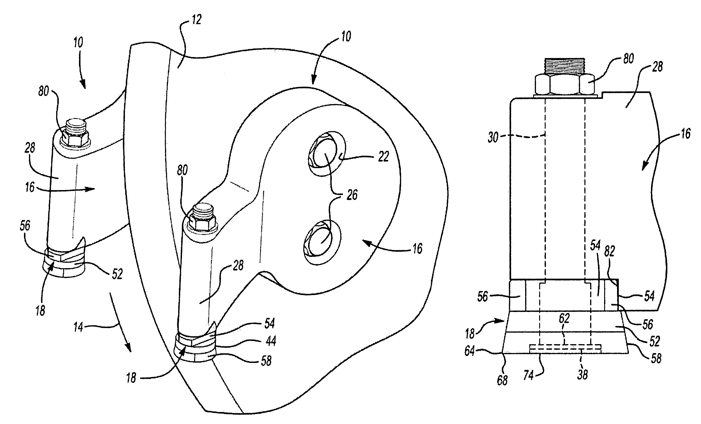
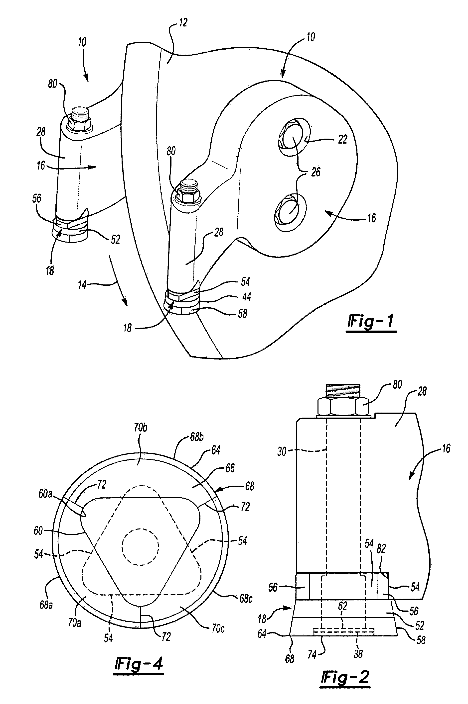
[0017]Referring now to the drawings, specifically FIGS. 1-2, a plurality of stump cutting tools, seen generally at 10, are shown attached in pairs to a cutting wheel 12 of a stump cutting apparatus (not shown.) The stump cutting apparatus supports the cutting wheel 12 in a known manner for rotation in the direction shown by the arrow 14. It should be understood that a stump cutting apparatus of this type is conventional and known in the art. Also, while shown herein with a cutting wheel 12, the present invention may be used with a tool assembly attached to a cutting drum.

[0018]Initially, it should be understood that the cutting tool assembly 10 includes a pocket or mounting block 16 and a cutting tooth 18. As illustrated in FIG. 1 the pockets or mounting blocks 16 are typically secured to the cutting wheel 12 in pairs. In the disclosed embodiment one of the pockets 16 includes a through bore or aperture having an adjacent countersunk portion 22 with the opposite pocket having a thre...


PUM


Abstract

A cutting tooth for use with a stump cutting apparatus wherein the cutting tooth has a removable and replaceable cutting bit. The cutting bit is removably and nonrotatably secured to a head of an elongated shank with the shank secured to a mounting block or pocket of a stump cutting tool. A support member having an indexing surface is also removably and nonrotatably secured to the head of the elongated shank. Accordingly, the support member enables indexing the cutting bit to expose and use a plurality of cutting edges located on the periphery of the cutting bit.

Description

CROSS-REFERENCE TO RELATED APPLICATIONS[0001]Not Applicable.BACKGROUND OF THE INVENTION[0002]1. Field of the Invention[0003]The present invention relates generally to a stump cutting apparatus and more specifically to a cutting tooth used with a stump cutting apparatus.[0004]2. Description of Related Art[0005]Stump cutters or stump cutting machines are generally known in the art and are used to cut or grind stumps. A typical stump cutter includes a plurality of cutting tools mounted to a rotatable cutting wheel or drum. Placing the wheel or drum against a stump and rotating it causes the cutting tools, and more particularly individual cutting teeth, to engage and cut away the stump. Tool holders, sometimes referred to as pockets, are used to secure the cutting teeth to the cutting wheel.[0006]Due to the harsh environment these cutting teeth are subjected to replacement of the cutting teeth is almost a continuous job. For example, contact with the ground surface rapidly dulls the cut...

Claims


Application Information

Patent Timeline
Patent Type & Authority Patents(United States)
IPC IPC(8): A01G23/06B27G13/00
CPCA01G23/067Y10T407/191Y10T407/192Y10T407/1946Y10T407/1926
Inventor GREEN, KEVIN J.
Owner GREEN KEVIN J
Why Eureka
Try Eureka