Al technical title is built by PatSnap Al team. It summarizes the technical point description of the patent document.
a rear door and control technology, applied in the field of heat management, can solve the problems of reducing the total amount of energy for a computing center, affecting the cooling effect of the cooling system,
Inactive Publication Date: 2009-02-03
IBM CORP
View PDF16 Cites 52 Cited by
Summary
Abstract
Description
Claims
Application Information
AI Technical Summary
This helps you quickly interpret patents by identifying the three key elements:
Problems solved by technology
Method used
Benefits of technology
Problems solved by technology
The increased computing power of today's computer systems leads to a proportionately increased energy requirement.
Thus, reducing the total amount of energy for a computing center is an important issue in the design and layout of the computing center.
Typical server rack rear doors are structured to blow the hot exhaust air horizontally into the room, leading to degraded total energy efficiency for cooling.
However, these rear doors utilize fans to move the hot air, which add to the total energy requirement for the computing center.
However, one common drawback to this set-up becomes apparent once one or more of the racks is removed from the computing center.
The mixing of air from both the hot and cold aisles causes a net decrease in the energy coefficient for total cooling, which could therefore lead to a cooling problem for third row 14 in general, and particularly for second server rack 17B in third row 14.
Method used
Image
Click on the blue label to locate the original text in one second.
Reading with bidirectional positioning of images and text.
Examples
Embodiment Construction
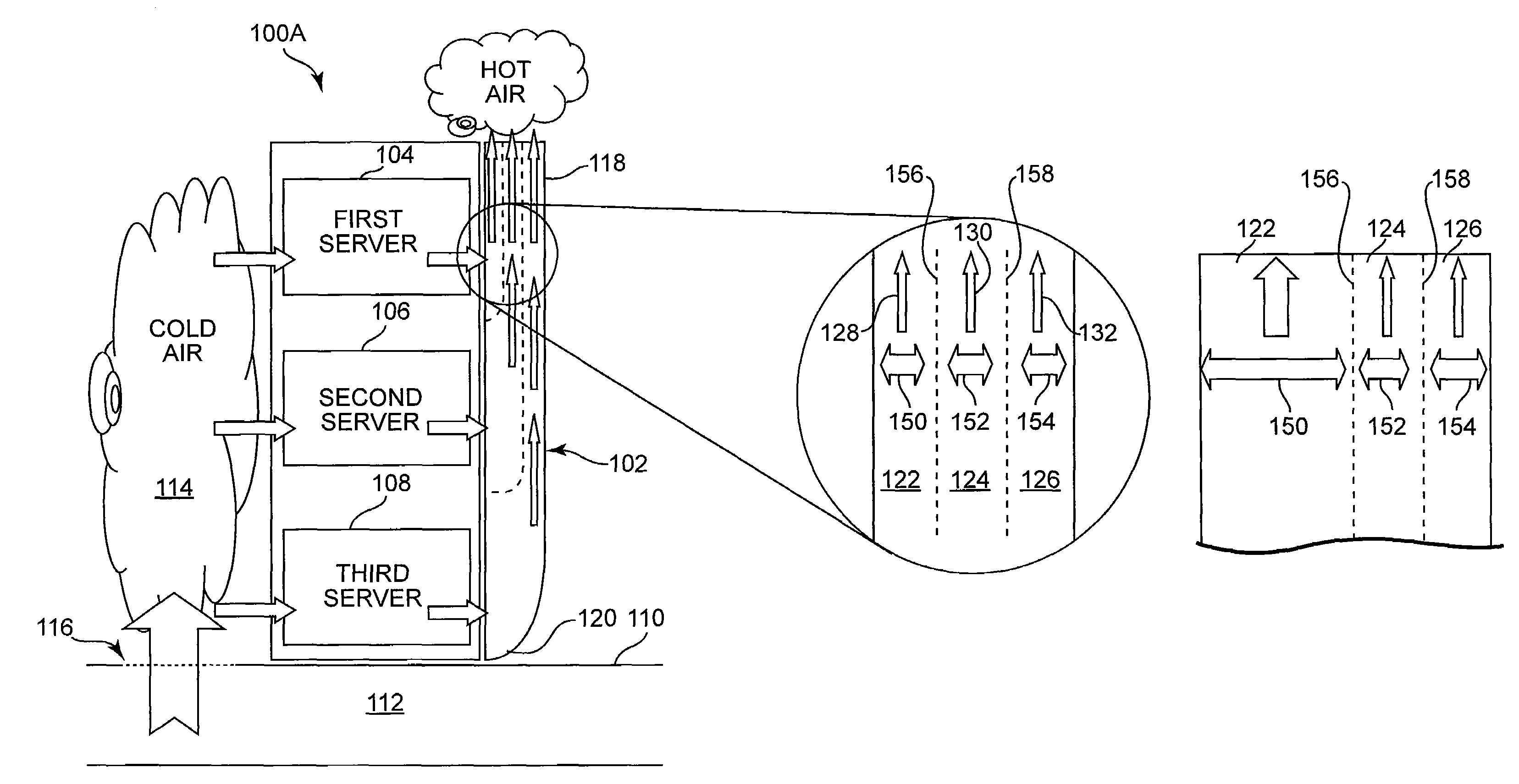
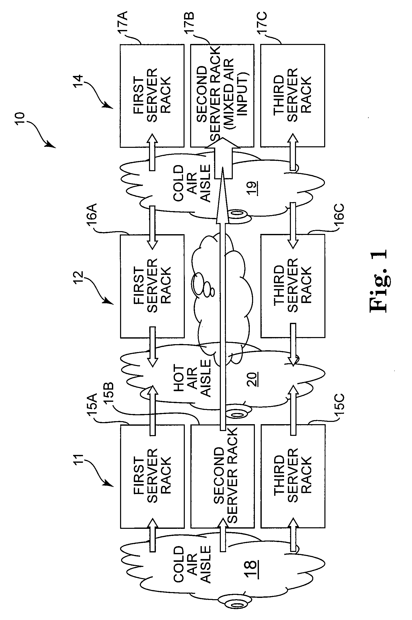
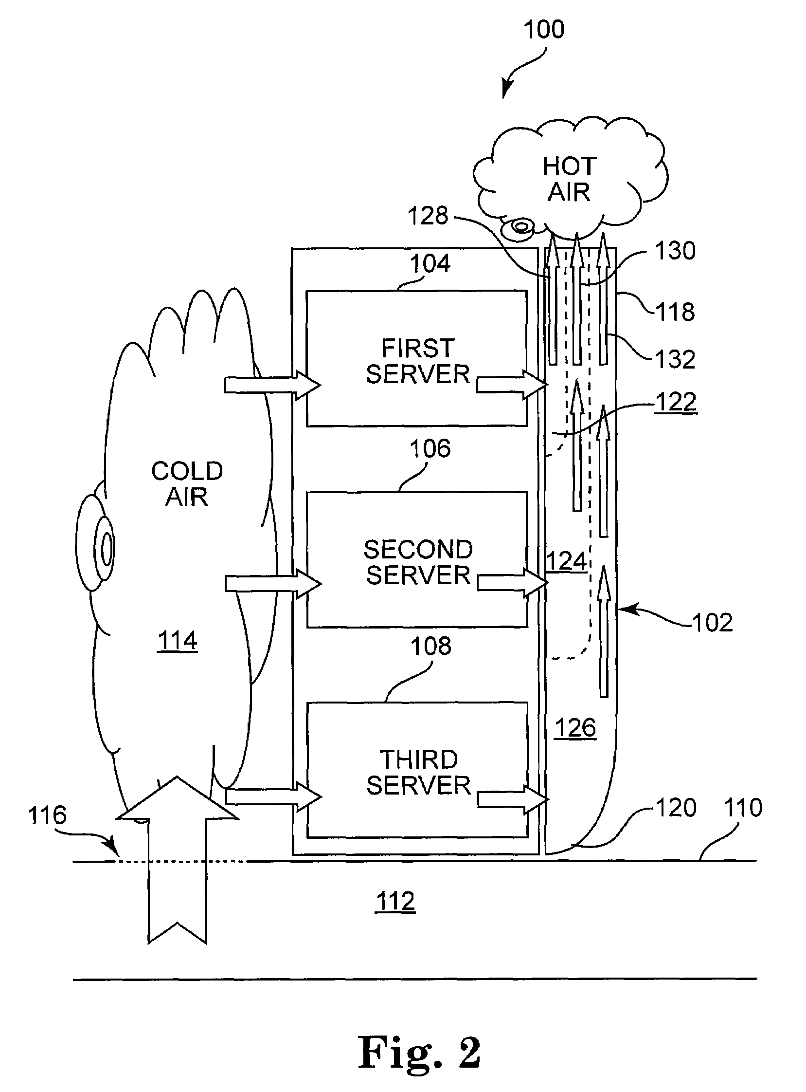
[0011]The present invention will be described in detail with reference to the figures below. However, generally speaking, the present invention encompasses a system and method for controlling the cooling air flow through a server rack. In particular, the present invention involves controlling the direction of hot air exiting a server rack with a configurable air exhaust system. In one exemplary embodiment, the hot air may be directed from the server rack toward air condition inlets in the ceiling of the computing center.
[0012]In accordance with various aspects of the present invention, the hot air exiting the server rack may be controlled so as to increase the total energy coefficient for cooling while simultaneously avoiding any mixing of the cold supply air and the hot exhaust air. The energy coefficient for cooling may generally be defined as the amount of cooling work divided by the amount of energy required to perform the cooling operation. As those skilled in the art will appr...
PUM
Abstract
A server rack system comprises a server rack, a raised floor cooling system, and an exhaust system. The server rack includes a base, a front side, a rear side, and an interior portion including first, second, and third server rows. The raised floor cooling system includes a floor surface, ductwork disposed below the floor surface, a blower unit, and a vent. The exhaust system is coupled to the rear side of the server rack and includes a top portion, a bottom portion, and first, second, and third adjustable exhaust channels. In particular, the first adjustable exhaust channel has a first adjustable width, an exhaust inlet aligned with the first server row, and an exhaust outlet at the top portion of the server rack; the second adjustable exhaust channel has a second adjustable width, an exhaust inlet aligned with the second server row, and an exhaust outlet at the top portion of the server rack; and the third adjustable exhaust channel has a third adjustable width, an exhaust inlet aligned with the third server row, and an exhaust outlet at the top portion of the server rack. The first and second adjustable exhaust channels are separated by a first moveable guide plate, and the second and third adjustable exhaust channels are separated by a second moveable guide plate. The first and second moveable guide plates are adjustable in order to vary the first, second, and third adjustable widths of the respective exhaust channels based upon an amount of hot air that must be exhausted through each channel.
Description
FIELD OF THE INVENTION[0001]The present invention relates in general to heat management, and more particularly, to a system and method for controlled hot air exhaust from the rear door of a server rack.BACKGROUND OF THE INVENTION[0002]The increased computing power of today's computer systems leads to a proportionately increased energy requirement. Thus, reducing the total amount of energy for a computing center is an important issue in the design and layout of the computing center. Typical server rack rear doors are structured to blow the hot exhaust air horizontally into the room, leading to degraded total energy efficiency for cooling. One possibility of reducing energy includes minimizing the mixing of cold supply air and hot exhaust air within the computing center. For example, there are rear doors which are designed to actively move the hot air from the server rack into a specific direction. However, these rear doors utilize fans to move the hot air, which add to the total ener...
Claims
Application Information
Patent Timeline
Application Date:The date an application was filed.
Publication Date:The date a patent or application was officially published.
First Publication Date:The earliest publication date of a patent with the same application number.
Issue Date:Publication date of the patent grant document.
PCT Entry Date:The Entry date of PCT National Phase.
Estimated Expiry Date:The statutory expiry date of a patent right according to the Patent Law, and it is the longest term of protection that the patent right can achieve without the termination of the patent right due to other reasons(Term extension factor has been taken into account ).
Invalid Date:Actual expiry date is based on effective date or publication date of legal transaction data of invalid patent.
Patent Type & Authority Patents(United States)
IPC IPC(8): H05K7/20F25D17/08
CPCH05K7/20745
Inventor GRIFFEL, MARCHUMMEL, JACQUESSCHAEFER, MICHAELUHL, KARL H.