Clamping device for clamping fittings in electric board channels

a technology of clamping device and clamping fitting, which is applied in the direction of machine supports, building components, domestic objects, etc., can solve the problems of prior approaches to the above intended applications, and achieve the effect of quick and easy connection of fittings, fast and simple movemen

Inactive Publication Date: 2009-02-17
CANALPLAST
View PDF4 Cites 8 Cited by
  • Summary
  • Abstract
  • Description
  • Claims
  • Application Information

AI Technical Summary

Benefits of technology

[0004]Accordingly, the aim of the present invention is to overcome the above mentioned problem, by providing a clamping device for clamping fittings in electric board channels, allowing to quickly and easily connect the fittings, by performing a very fast and simple movement.
[0005]Within the scope of the above mentioned aim, a main object of the invention is to provide such a clamping device which, owing to its specifically designed constructional characteristics, is very reliable and safe in operation.
[0006]Another object of the present invention is to provide such a clamping device which can be easily made starting from easily commercially available elements and materials and which, moreover, is very competitive from a mere economic standpoint.

Problems solved by technology

However, prior approaches for the above intended applications, are affected by great problems related to a proper coupling of the electric fittings, since it is necessary to perform very long and complex connection operations.

Method used


Image

  • Clamping device for clamping fittings in electric board channels
  • Clamping device for clamping fittings in electric board channels
  • Clamping device for clamping fittings in electric board channels

Examples


Embodiment Construction

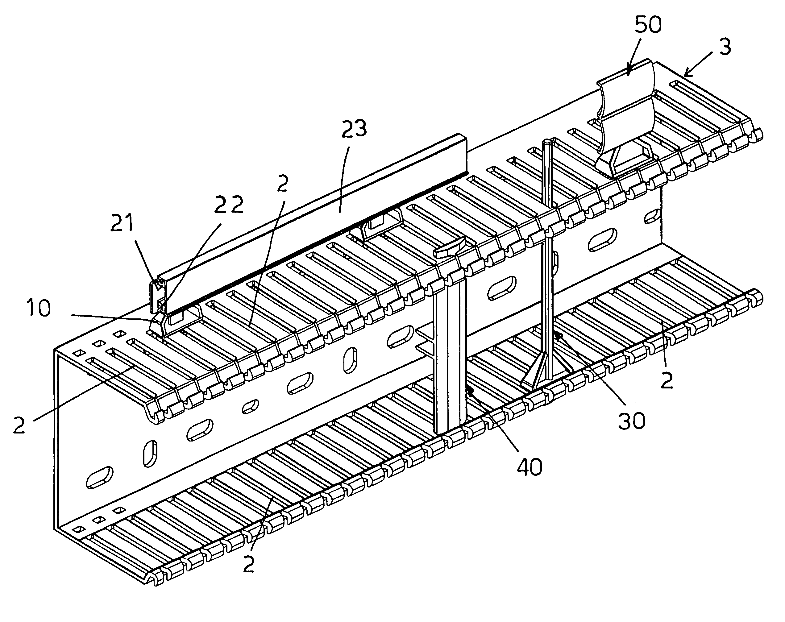
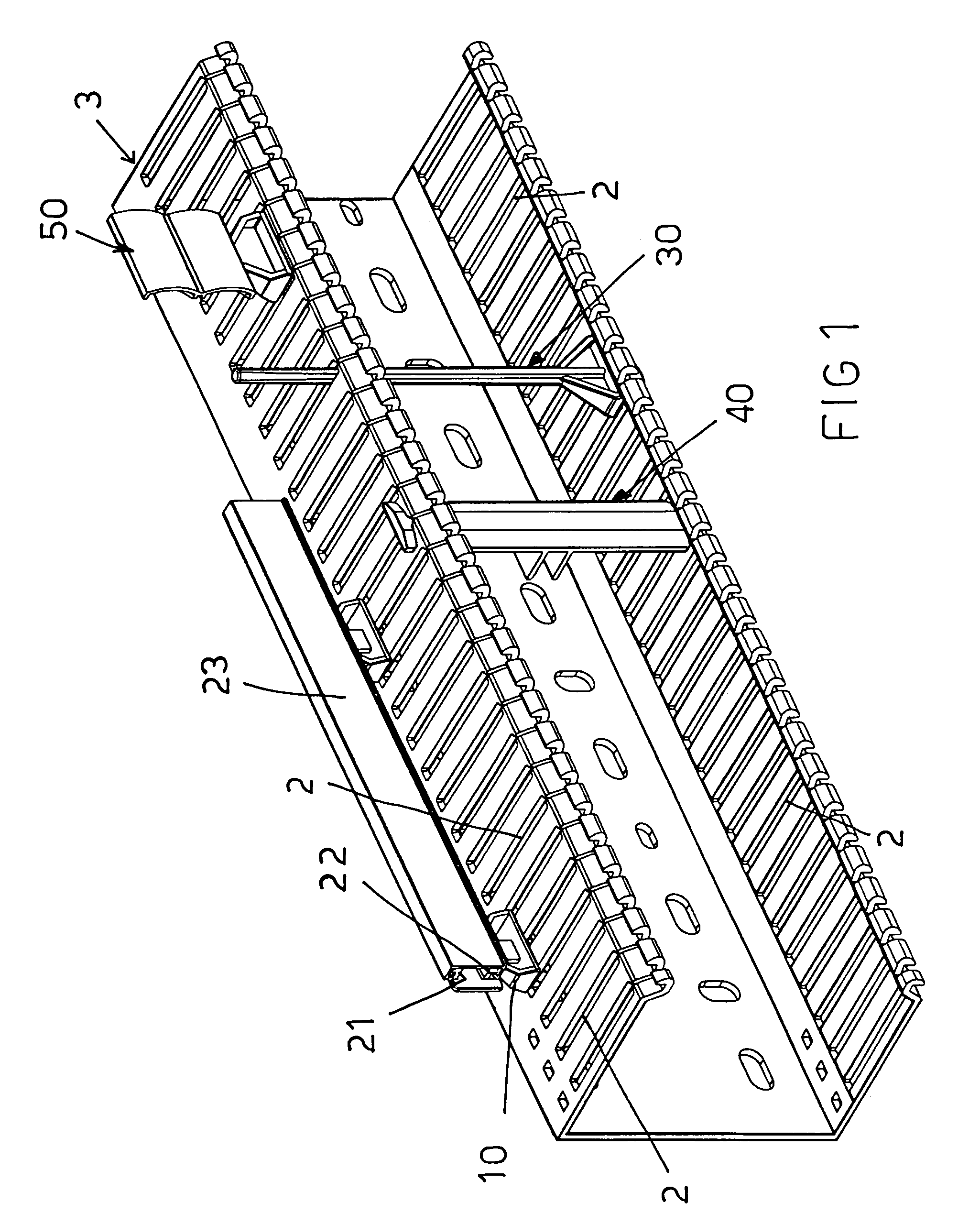
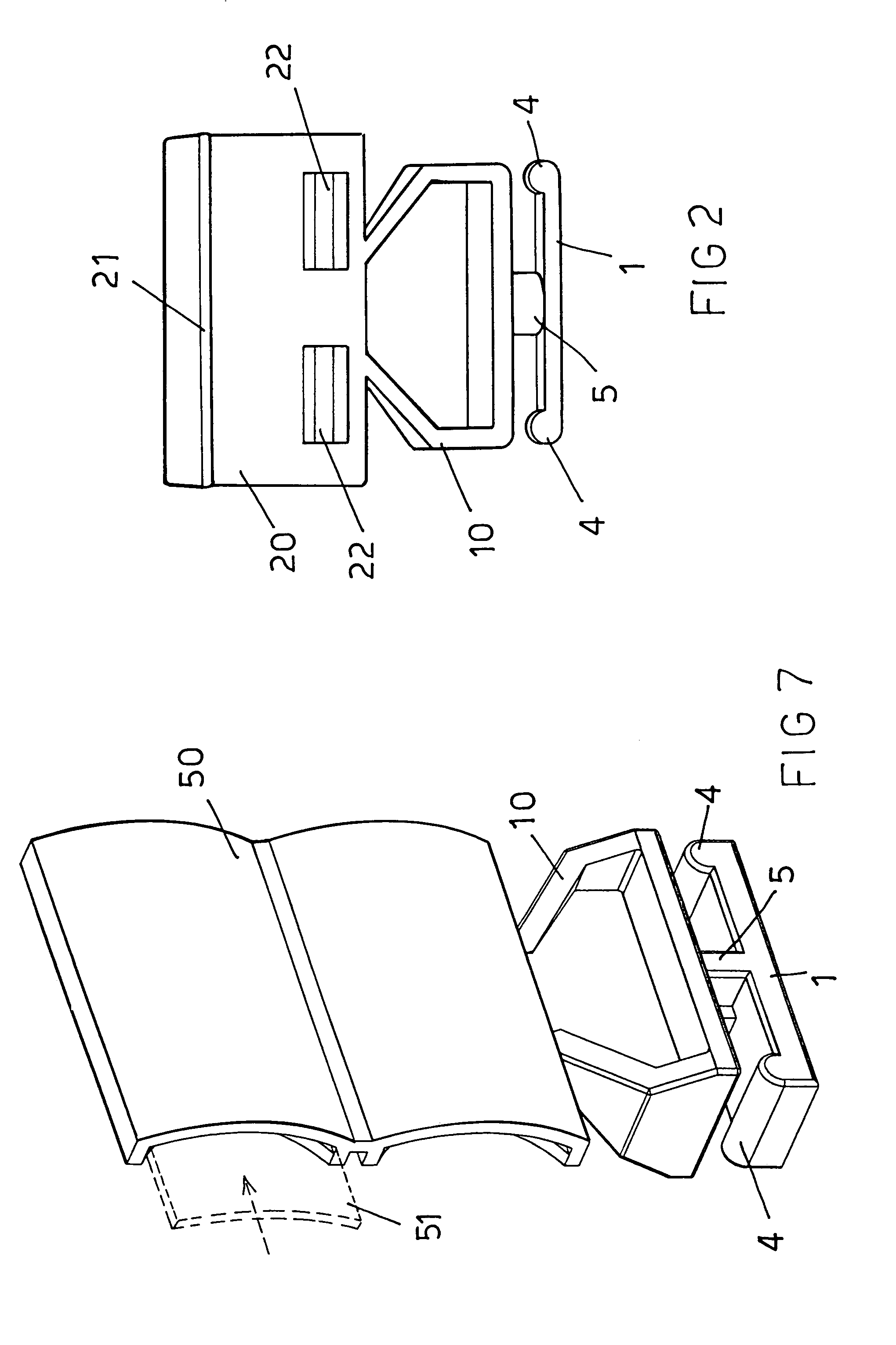
[0016]With reference to the number references of the above mentioned figures, the clamping device for clamping fittings in electric board channels, according to the present invention, comprises a rod or bar element, generally indicated by the reference number 1, which has an elongated configuration, for engagement in cavities 2 provided in conventional channels 3.

[0017]More specifically, said rod element comprises, at the free end portions thereof, upward projecting elements 4.

[0018]At a middle portion of said rod element 1, an end piece 5, of restrained configuration, and having a width substantially corresponding to the width of the cavities 2, is herein provided.

[0019]To the thus constructed clamping device, is connected a supporting body, generally indicated by the reference number 10, for coupling several fittings thereto.

[0020]More specifically, FIGS. 2 and 3 show a plate fitting 20, including opposite tooth elements 21 and 22, allowing an adhesive label bearing rod 23 to be e...


PUM


Abstract

The invention relates to a clamping device for clamping fittings in electric board channels, comprising a rod element which can be engaged in a cavity formed in electric component channels and coupled, through an end piece, to a fitting supporting body, the supporting body being adapted to be locked on the channels by causing the supporting body to turn about an axis substantially perpendicular to the rod element.

Description

BACKGROUND OF THE INVENTION[0001]The present invention relates to a clamping device for clamping fittings in electric board channels and the like.[0002]As is known, channels to be used for receiving cables for coupling electric fitting boards, generally comprise cross cavities and slots, allowing the electric fittings to be easily connected, and operating to enhance the operating properties of the receiving channel, while holding the cables arranged therein in an ordered condition.[0003]However, prior approaches for the above intended applications, are affected by great problems related to a proper coupling of the electric fittings, since it is necessary to perform very long and complex connection operations.SUMMARY OF THE INVENTION[0004]Accordingly, the aim of the present invention is to overcome the above mentioned problem, by providing a clamping device for clamping fittings in electric board channels, allowing to quickly and easily connect the fittings, by performing a very fast...

Claims


Application Information

Patent Timeline
Patent Type & Authority Patents(United States)
IPC IPC(8): H02G3/04
CPCH02G3/0431H02G3/045
Inventor VILLI, PIERGIORGIO
Owner CANALPLAST
Why Eureka
Try Eureka