Personal table

Inactive Publication Date: 2006-11-02
LIFETIME PRODUCTS
View PDF61 Cites 0 Cited by
  • Summary
  • Abstract
  • Description
  • Claims
  • Application Information

AI Technical Summary

Benefits of technology

[0033] Still another aspect is a table that may include a frame and the frame may be sized and configured to secure one of the table legs or a portion of the support structure in a fixed position. For example, the frame may include two side rails and a portion of one of the table legs or support structure may be secured in a fixed position by the side rails. In particular, an upper portion of a table leg or support structure may be disposed between the side rails and a lower portion of the table top. Additionally, a channel or groove may be formed in the lower portion of the table top to receive at least a portion of the upper portion of the table leg or support structure. Advantageously, this may allow the leg or portion of the support structure to be quickly and easily secured in a fixed position, and this may also allow the legs to be positioned near or adjacent to the lower portion of the table top when the legs are in the collapsed position. Significantly, this may allow the legs to fold flat against the lower portion of the table top, which may facilitate shipping and storage of the table.
[0034] Yet another aspect is a table that may be adjustable in height by selectively connecting the table legs or support assembly to various receiving portions. The receiving portions, for example, may include a channel or groove formed in the lower portion of the table top. The receiving portions may also include retaining portions disposed at opposing ends of the channels or grooves. In particular, the receiving portions may extend across a portion of the lower portion of the table top and the retaining portions may include openings that are sized and configured to receiving the ends of a table leg or support assembly. The openings may be at least partially defined by a portion of a frame, such as the side rails. Specifically, a channel or groove may be disposed on one side of the retaining portion and the side rail may be disposed on the other side to define at least a portion the opening. Advantageously, this may allow the table leg or support assembly to be quickly and easily connected to the table top. In addition, this may also allow the legs to fold flat against the lower portion of the table top, which may facilitate shipping and storage of the table. Further, this may allow the legs to be securely connected to the table top, which may help create a strong and sturdy table.
[0035] A further aspect is a table that may include receivi

Problems solved by technology

Table tops constructed from wood, particle board or metal, however, are often relatively heavy and this may make the table awkward or difficult to move.
Conventional table tops constructed from wood or metal are also relatively expensive and the table tops must generally be treated or finished before use.
In addition, these relatively heavy table tops increase the cost of transportation, shipping, and storage of the tables.
Disadvantageously, these light-weight table tops frequently require reinforcing members or other structural parts such as brackets, support members and the like to strengthen the table top.
These additional parts may increase the strength of the table top, but these additional parts also increase the weight of the table.
In addition, these additional parts increase manufacturing costs and require additional time to assemble the table.
Furthermore, these additional parts may have sharp edges that can injure the user's arms or legs.
Disadvantageously, because the telescoping assemblies include overlapping components, the assembly is relatively heavy.
Additionally, conventional tables may use other mechanisms to allow the height of the table to be adjusted, but these devices are often relatively complex and require additional parts, which generally increases the amount of time required to manufacture the table and the costs to assemble the table.
These complex designs may also result in tables that are relatively difficult for the consumer to use and these tables may require a substantial amount of time

Method used


Image

  • Personal table
  • Personal table
  • Personal table

Examples


Example

[0051] The present invention is directed towards a table and, in particular, to a table that is intended to be used by a single user at one time. The principles of the present invention, however, are not limited to a table intended for use by an individual user. It will be understood that, in light of the present disclosure, the table can be used by more than one user at any given time.

[0052] Additionally, to assist in the description of the table, words such as top, bottom, front, rear, right and left are used to describe the accompanying figures. It will be appreciated, however, that the table can be located in a variety of desired positions—including various angles, sideways and even upside down. A detailed description of the table now follows.

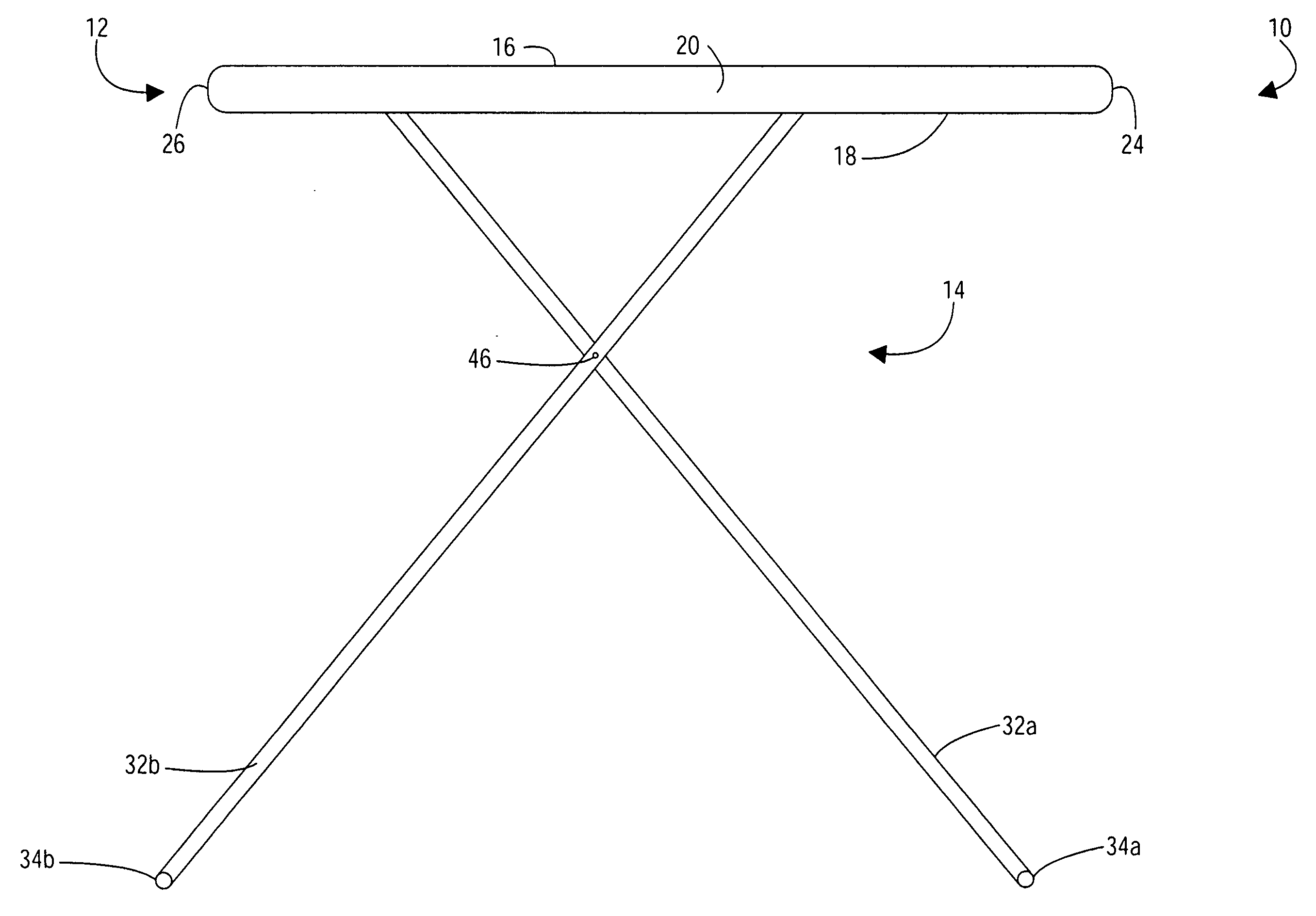
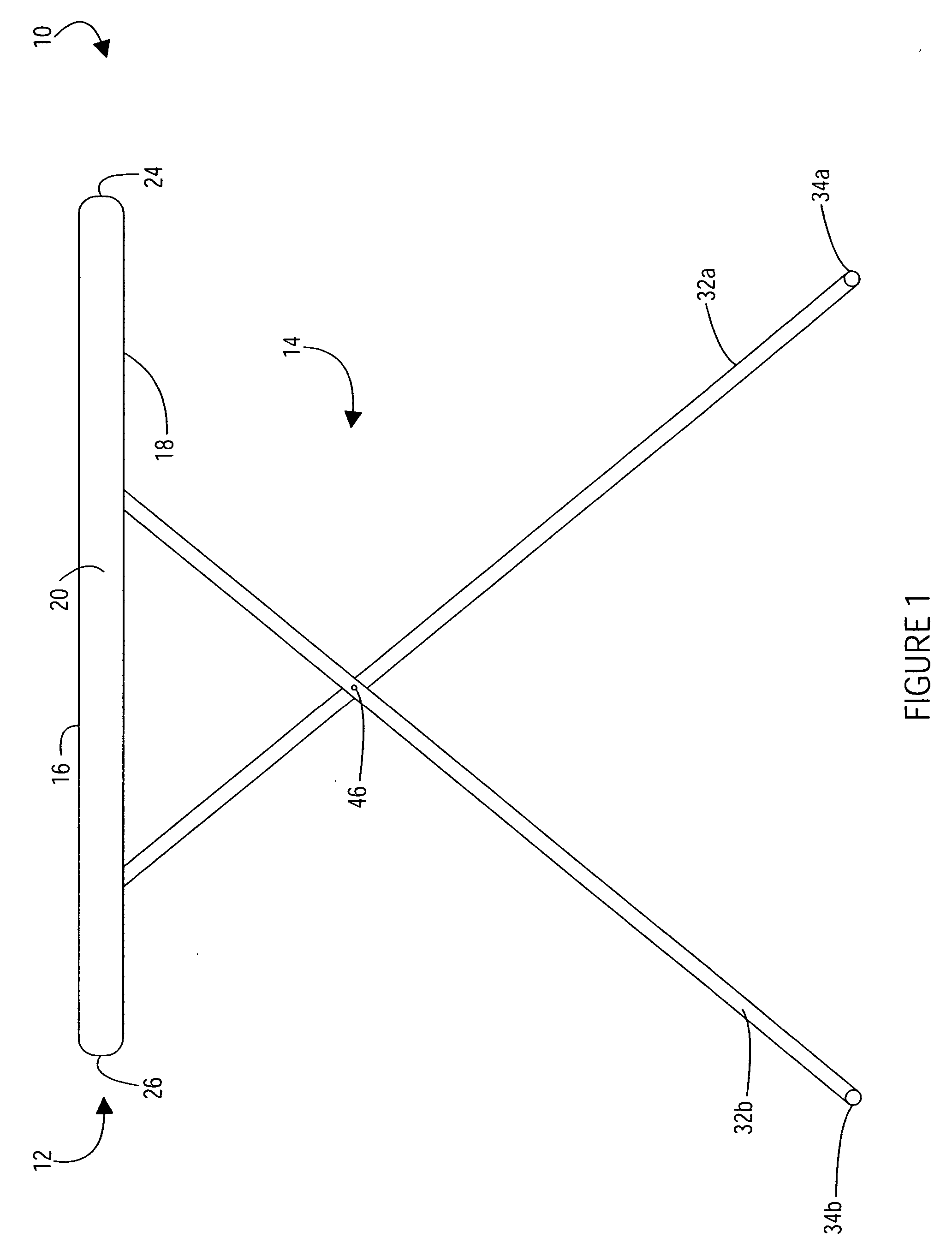
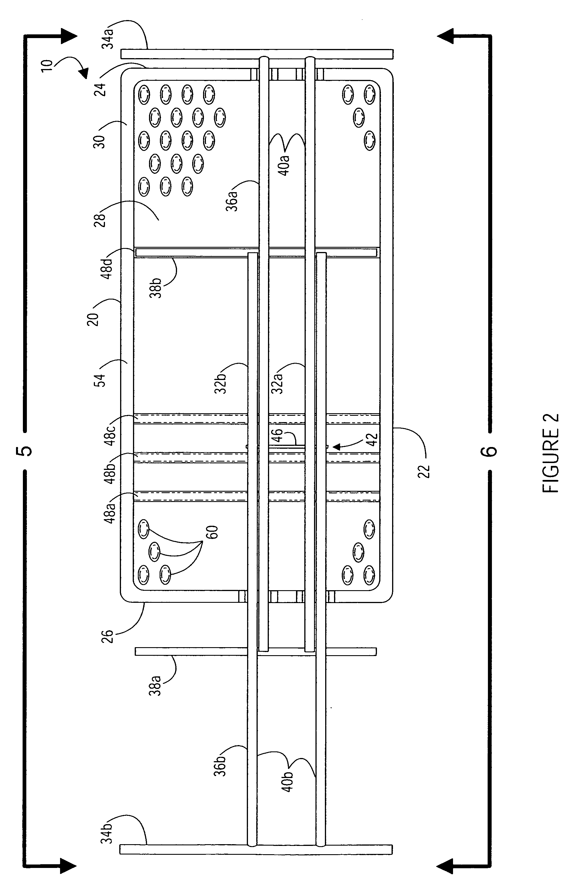
[0053] As seen in FIGS. 1 and 2, an exemplary table 10 is shown. The table 10 is preferably a relatively small-sized table that is intended for use by a single person at one time. Advantageously, because the table 10 is sized and configur...


PUM


Abstract

A personal table is provided having a table top supported by a support assembly. The table top is preferably constructed from blow-molded plastic and the support assembly preferably includes a first leg and a second leg that are pivotally connected. The legs desirably have a generally X-shaped configuration when the legs are placed in an upright position and the legs can be collapsed into a storage position. Each of the legs may include a lower portion, a body portion and an upper portion that is preferably selectively connected to the table top. The legs, for example, can be connected to the table top by inserting the upper portions of the legs into leg receiving recesses formed in the table top. The leg receiving recesses are preferably integrally formed in the bottom surface of the table top as part of a one-piece construction. Desirably, a plurality of leg receiving recesses are formed in the bottom surface of the table top and the legs can be selectively attached to the leg receiving recesses in order to vary the height of the table.

Description

CROSS-REFERENCE TO RELATED APPLICATIONS [0001] This application claims priority to and the benefit of U.S. provisional patent application Ser. No. 60 / 660,526, filed Mar. 10, 2005 and entitled PERSONAL TABLE. [0002] This application is also a continuation-in-part of U.S. patent application Ser. No. 11 / 038,375, filed Jan. 18, 2005, entitled PERSONAL TABLE; which is a continuation of U.S. patent application Ser. No. 10 / 340,018, filed Jan. 9, 2003, entitled PERSONAL TABLE, now U.S. Pat. No. 6,912,961; which claims priority to and the benefit of U.S. provisional patent application Ser. No. 60 / 347,556, filed Jan. 9, 2002, entitled PERSONAL TABLE; U.S. provisional patent application Ser. No. 60 / 364,712, filed Mar. 14, 2002, entitled PERSONAL TABLE; and U.S. provisional patent application Ser. No. 60 / 421,221, filed Oct. 25, 2002, entitled PERSONAL TABLE. In addition, U.S. patent application Ser. No. 10 / 340,018 is a continuation-in-part of U.S. design patent application serial no. 29 / 167,624...

Claims


Application Information

Patent Timeline
IPC IPC(8): A47B3/02
CPCA47B9/16A47B3/12
Inventor WINTER, DAVID C.JONES, JAYNYE, STEPHEN F.SMITH, BRANDONASHBY, KENTSTRONG, L. CURTISNYE, S. CURTISHANEY, THAYNE B.JIN, JY YOUNG
Owner LIFETIME PRODUCTS
Why Eureka
Try Eureka