Precision notch machining fixture and method

a technology of machining fixture and notch, which is applied in the direction of manufacturing tools, metal-working machine components, positioning apparatuses, etc., can solve the problems of time-consuming, extra labor on the part of die maker or machinist, and the process of setting up the plate after, so as to achieve quick and easy securement of the piece

Inactive Publication Date: 2010-01-05
BOERSMA DREW H
View PDF3 Cites 0 Cited by
  • Summary
  • Abstract
  • Description
  • Claims
  • Application Information

AI Technical Summary

Benefits of technology

[0004]The present invention provides a way to quickly and easily secure a piece of hot-roll steel to a machine tool for machining. The part being machined can be machined on a first side and then flipped over for machining on a second side. The fixture / device of the present invention securely holds the part for machining, and also precisely locates the part without conventional manual set-up. The part is made from a piece of hot-roll steel that is cut from a larger sheet or plate of stock utilizing a flame-cutting process. The perimeter of the piece is flame-cut to the required size and shape for the part being made, and one or more locating / supporting features such as notches are flame-cut into the perimeter / edge of the piece. The notches preferably have a U-shape in plan view, and the notches are spaced apart around the perimeter of the piece of steel.
[0007]After machining on a first side of the part is completed and precision notches are machined at the flame-cut notches, the part is flipped over (i.e. rotated 180° relative to a horizontal axis) and the part is again secured to the plate utilizing the support members and clamp members. The support members include a small protrusion at an end of the notch-engaging portions of the support members having a size and shape closely corresponding to the size and shape of the precision notches. The small protrusions are positioned in the precision notches, and the clamp members are utilized to clamp the part in place on the plate. The small protrusions engage the precision notches and thereby precisely position the part relative to the support members. Because the support members are precisely located on the plate by the key-type feature which is received in the T-slots, the position of the part on the mill is therefore precisely controlled, and the time and effort required to secure and position the part on the second side is greatly reduced.

Problems solved by technology

The features machined into both sides of the part often need to be located precisely relative to one another, and the process of setting up the plate after flipping it over therefore tends to be time-consuming because the plate needs to be precisely located (“set up”) utilizing the features previously machined into the component.
This set-up time results in not only extra labor on the part of the die maker or machinist, but also results in down time for the machine during the set-up operation.

Method used


Image

  • Precision notch machining fixture and method
  • Precision notch machining fixture and method
  • Precision notch machining fixture and method

Examples


Embodiment Construction

[0017]This application is related to co-pending U.S. patent application Ser. No. 11 / 709,951, filed on Feb. 23, 2007, entitled MODULAR TOOLING SYSTEM A ND METHOD, the entire contents of which are incorporated herein by reference.

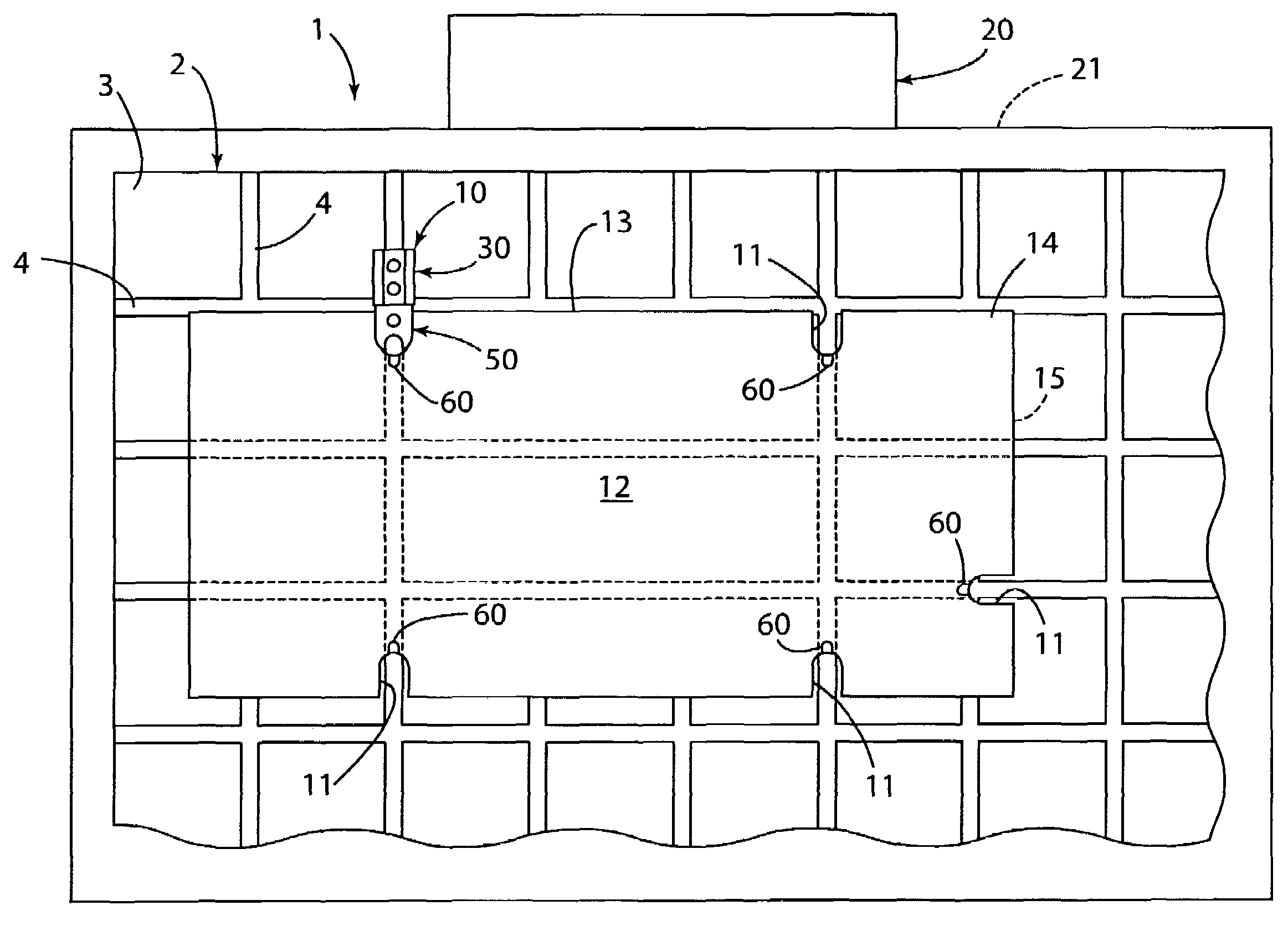
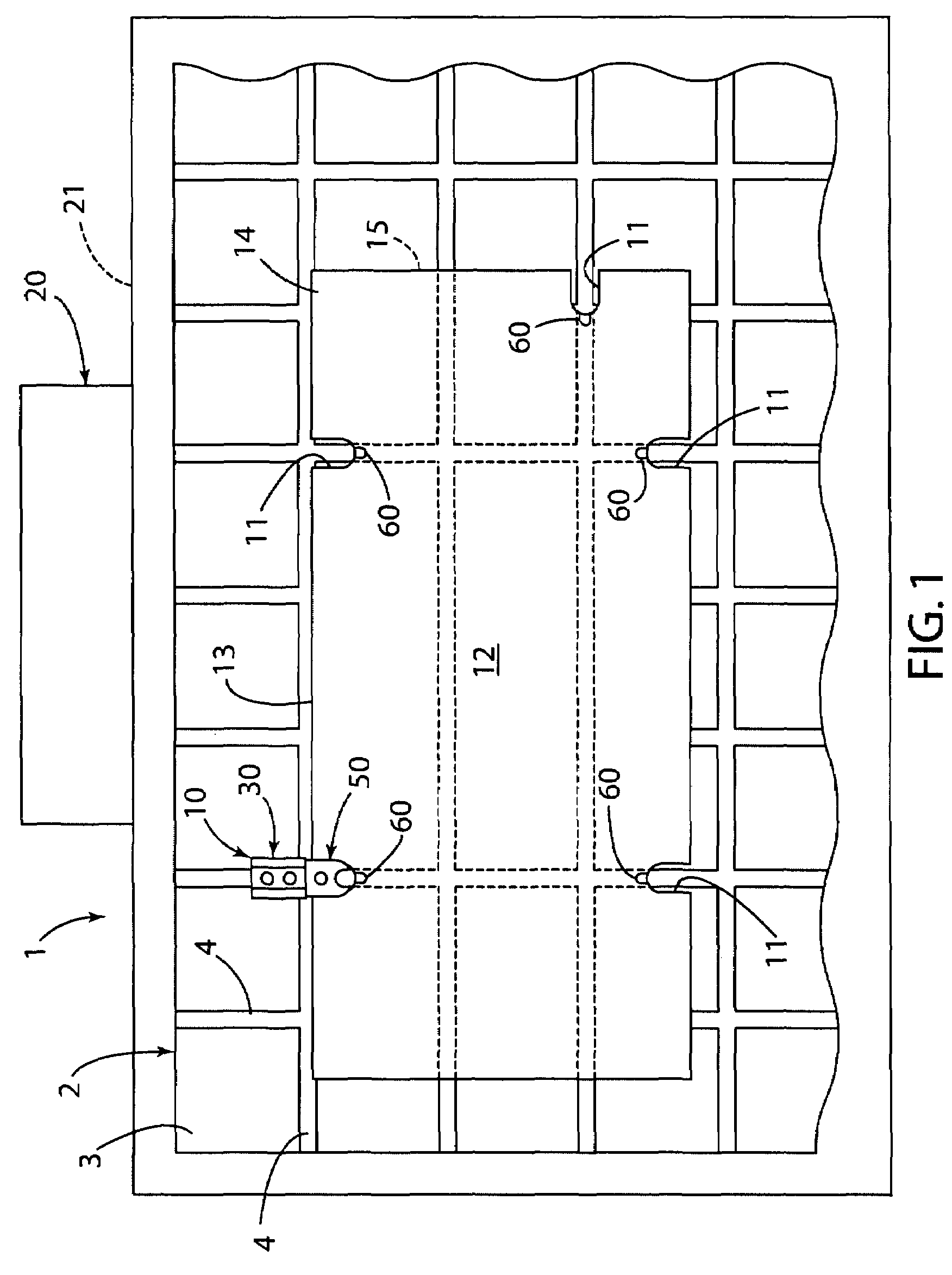
[0018]For purposes of description herein, the terms “upper,”“lower,”“right,”“left,”“rear,”“front,”“vertical,”“horizontal,” and derivatives thereof shall relate to the invention as oriented in FIG. 1. However, it is to be understood that the invention may assume various alternative orientations and step sequences, except where expressly specified to the contrary. It is also to be understood that the specific devices and processes illustrated in the attached drawings and described in the following specification are simply exemplary embodiments of the inventive concepts defined in the appended claims. Hence, specific dimensions and other physical characteristics relating to the embodiments disclosed herein are not to be considered as limiting, unless the claims ...


PUM

PropertyMeasurementUnit
distanceaaaaaaaaaa
sizeaaaaaaaaaa
movementaaaaaaaaaa

Abstract

A fixture includes an enlarged plate having slots in an upper surface, and support members are secured to the plate at the slots. The fixture is utilized to machine parts that are initially flame-cut from a large plate / sheet of hot-roll steel. A plurality of notches are flame-cut into the perimeter of the part. The support members engage the flame-cut slots to secure the part to the plate for machining a first side of the part. Precision notches are machined into the part, and precisely-shaped protrusions on the support members are closely received in the precision notches to precisely locate the part for further machining on a second side thereof.

Description

BACKGROUND OF THE INVENTION[0001]Various types of dies for stamping / forming sheet parts from sheet metal have been developed. Such dies are typically custom made to produce a particular part by a skilled tradesman. Numerous components of such dies are often made from hot-roll steel plate. Such components are typically rough-cut from a large plate of hot-roll steel utilizing a flame-cutting process, and the upper and lower surfaces of the plate are ground flat in a “Blanchard” grinder or the like. Die shops typically receive the rough-cut component from the supplier with flat ground parallel upper and lower surfaces, and a rough-cut perimeter having the approximate size and shape of the finished stripper or other such component. In general, hot-roll steel plate and the like can be rough cut more quickly and economically by flame-cutting than by sawing or the like. Thus, flame-cutting the part to the approximate final shape and size reduces the amount of labor by a skilled tradesman t...

Claims


Application Information

Patent Timeline
Patent Type & Authority Patents(United States)
IPC IPC(8): B23D81/00
CPCB25B5/10B25B5/163
Inventor BOERSMA, DREW H.
Owner BOERSMA DREW H
Why Eureka
Try Eureka