Adaptive mounting bracket assembly

Active Publication Date: 2019-06-13
THE BOEING CO
View PDF0 Cites 0 Cited by
  • Summary
  • Abstract
  • Description
  • Claims
  • Application Information

AI Technical Summary

Benefits of technology

The patent text describes a method for securely attaching a mounting bracket to a structure. The method involves using a securing cradle with a chamber for holding a pivot arm and a locking arm. The pivot arm and locking arm are connected by a first hinge and a second hinge, allowing them to move into an over-center position. This position is securely locked into place on the structure, providing a secure attachment.

Problems solved by technology

Typically, complex engineering analyses are used to determine precise locations for the mounting holes, fasteners, and the nature of such fasteners because holes, for example, de-rate a strength capability of the underlying structure.
Further, the process of securing the components to the structures may be time and labor intensive, as individuals need to align fasteners with the mounting holes, align mounting brackets to the structures, and use one or more tools to secure the mounting brackets to the structures and / or components via the fasteners.
Additionally, various locations within an aircraft may not be spacious enough to allow an individual to easily manipulate a tool and / or the mounting bracket, thereby further complicating an installation process.
However, the known mounting bracket may exert a relatively great amount of pressure into portions of the insulation blanket during installation and / or removal, and may tear, puncture, or otherwise damage the insulation blanket.

Method used


Image

  • Adaptive mounting bracket assembly
  • Adaptive mounting bracket assembly
  • Adaptive mounting bracket assembly

Examples


Embodiment Construction

[0016]The foregoing summary, as well as the following detailed description of certain embodiments will be better understood when read in conjunction with the appended drawings. As used herein, an element or step recited in the singular and preceded by the word “a” or “an” should be understood as not necessarily excluding the plural of the elements or steps. Further, references to “one embodiment” are not intended to be interpreted as excluding the existence of additional embodiments that also incorporate the recited features. Moreover, unless explicitly stated to the contrary, embodiments “comprising” or “having” an element or a plurality of elements having a particular condition may include additional elements not having that condition.

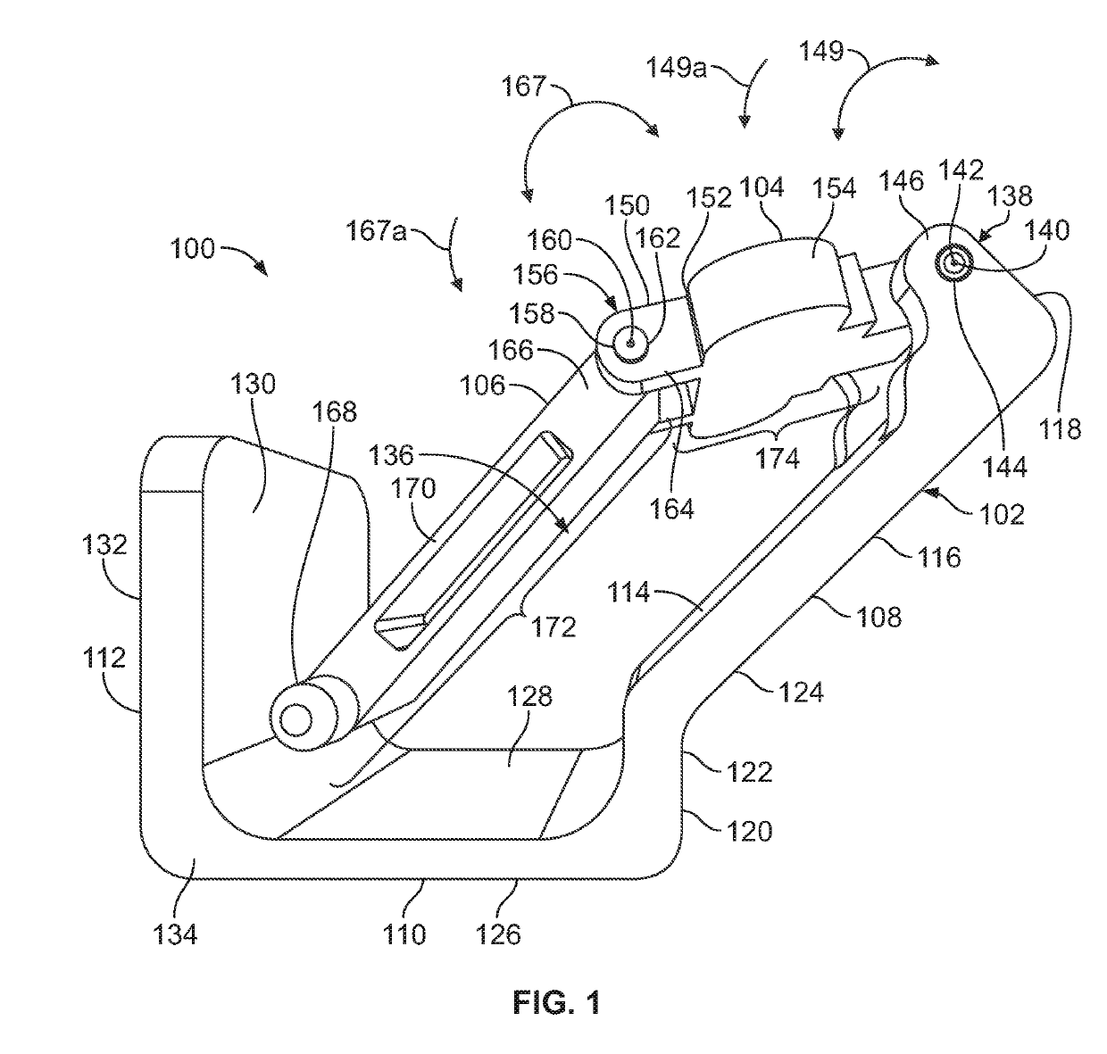
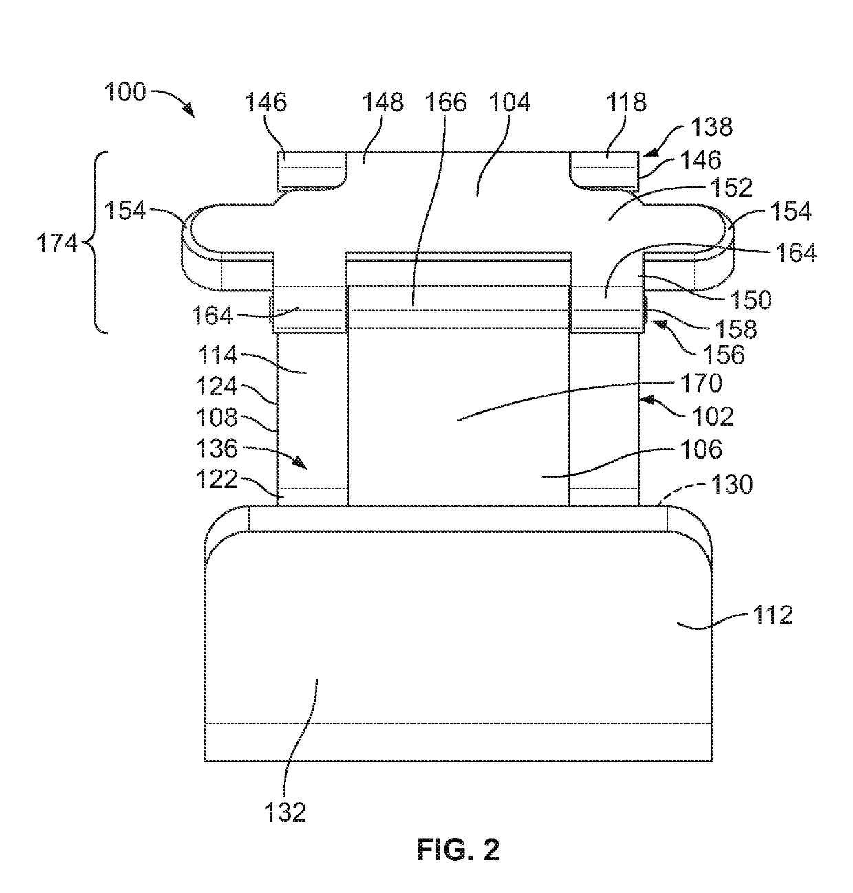
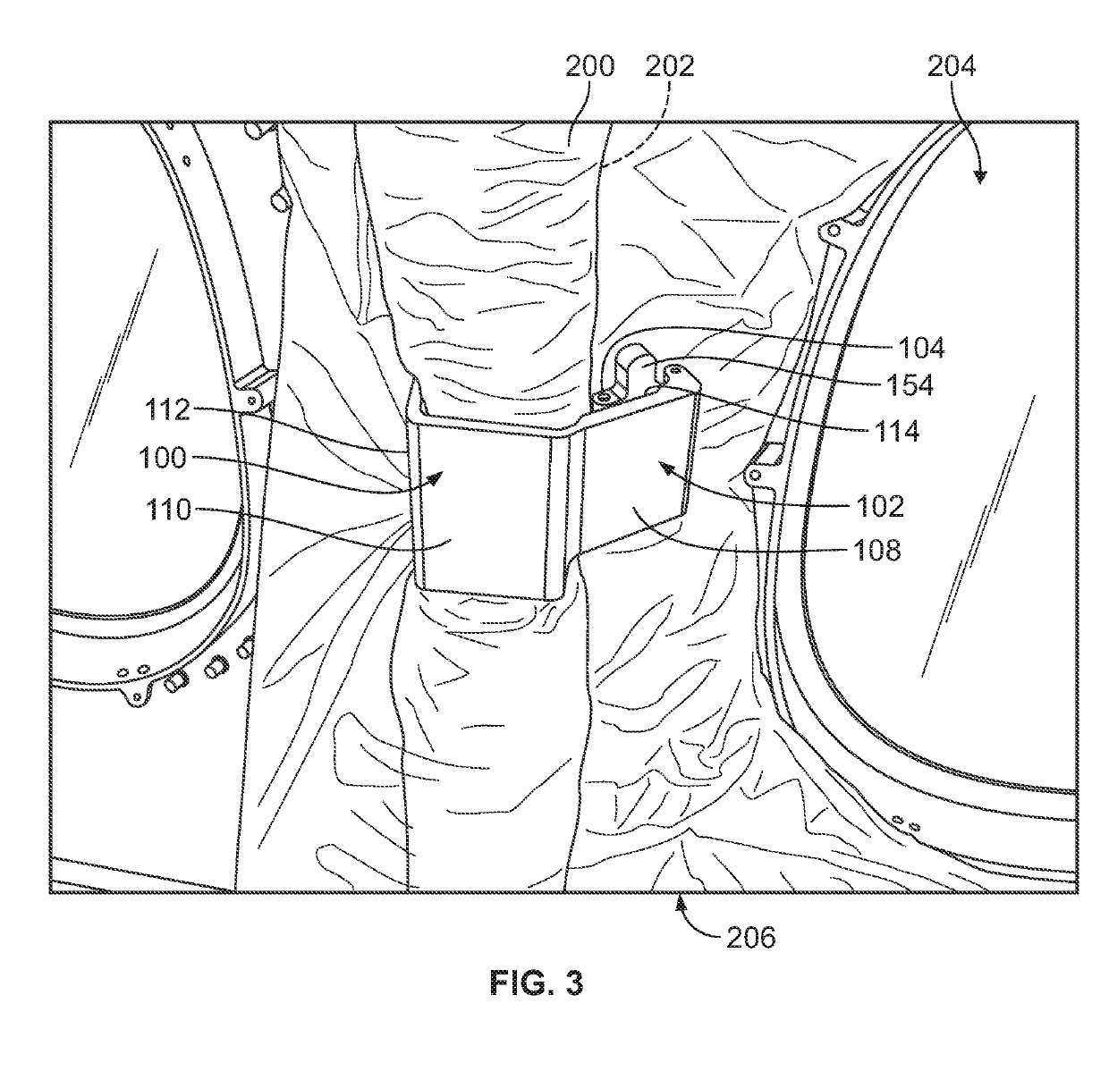
[0017]Certain embodiments of the present disclosure provide an adaptive mounting bracket assembly that is configured to secure onto a structure, such as within an internal cabin of an aircraft. The adaptive mounting bracket assembly is configured to ...


PUM


Abstract

A mounting bracket assembly is configured to securely couple to a structure. The mounting bracket assembly includes a securing cradle defining a securing chamber, a pivot arm that pivotally couples to the securing cradle through a first hinge, and a locking arm that pivotally couples to the pivot arm through a second hinge. The pivot arm and the locking arm are configured to pivotally move via the first hinge and the second hinge into an over-center securing position within the securing chamber to securely lock the mounting bracket assembly to the structure.

Description

FIELD OF THE DISCLOSURE[0001]Embodiments of the present disclosure generally relate to adaptive mounting bracket assemblies, and, more particularly, to adaptive mounting bracket assemblies that are configured to be quickly and easily secured to structures, such as within an internal cabin of a vehicle.BACKGROUND OF THE DISCLOSURE[0002]A vehicle, such as a commercial aircraft, includes numerous components that are secured to one another. For example, stringers or frames are secured to outer skins, and thereby form portions of a fuselage, for example. Various components may be secured to the frames. In order to secure various components to structures of an aircraft, mounting holes that are configured to receive fasteners (such as bolts, screws, and / or the like) are formed through the structures and / or the components. Typically, complex engineering analyses are used to determine precise locations for the mounting holes, fasteners, and the nature of such fasteners because holes, for exa...

Claims


Application Information

Patent Timeline
IPC IPC(8): F16M13/02
CPCF16M13/022B64D9/00B64C1/064B64C1/40F16B2/10B64C1/403B64C1/00
Inventor ROEDER, RAYMONDYAP, ALYSSA L.PRICE, WADE T.SCHWITTERS, CHRISTOPHER L.OLSEN, BRUCE R.
Owner THE BOEING CO
Why Eureka
Try Eureka