Serially controllable LED lighting systems

a technology of led lighting and controllable parts, applied in the direction of lighting and heating apparatus, lighting applications, coupling device connections, etc., can solve the problems of difficult replacement of led lights, complicated and/or cumbersome assemblies, and difficulty in ensuring proper connections, etc., to achieve the effect of reducing damage or breakage, and reducing the degree of flexibility

Active Publication Date: 2009-02-24
HAYWARD IND INC
View PDF9 Cites 28 Cited by
  • Summary
  • Abstract
  • Description
  • Claims
  • Application Information

AI Technical Summary

Benefits of technology

[0020]In another aspect of the invention, the basal portion of the plug member may be structured to perform a strain relief function to deter damage to or breakage of the connection between the connector cable and the light emitting diode. For example, the

Problems solved by technology

For instance, because of the small physical form, lamp replacement (LED replacement) may be difficult where the LED assemblies are in an enclosed, confined or hard-to access.
Surface mounted LED lighting systems of the prior art have addressed the problems associated with replacing the LED light source in various ways, including the use of specialized lenses, sockets and/or sleeves that may render such assemblies complicated and/or cumbersome.
Als

Method used


Image

  • Serially controllable LED lighting systems
  • Serially controllable LED lighting systems
  • Serially controllable LED lighting systems

Examples


Embodiment Construction

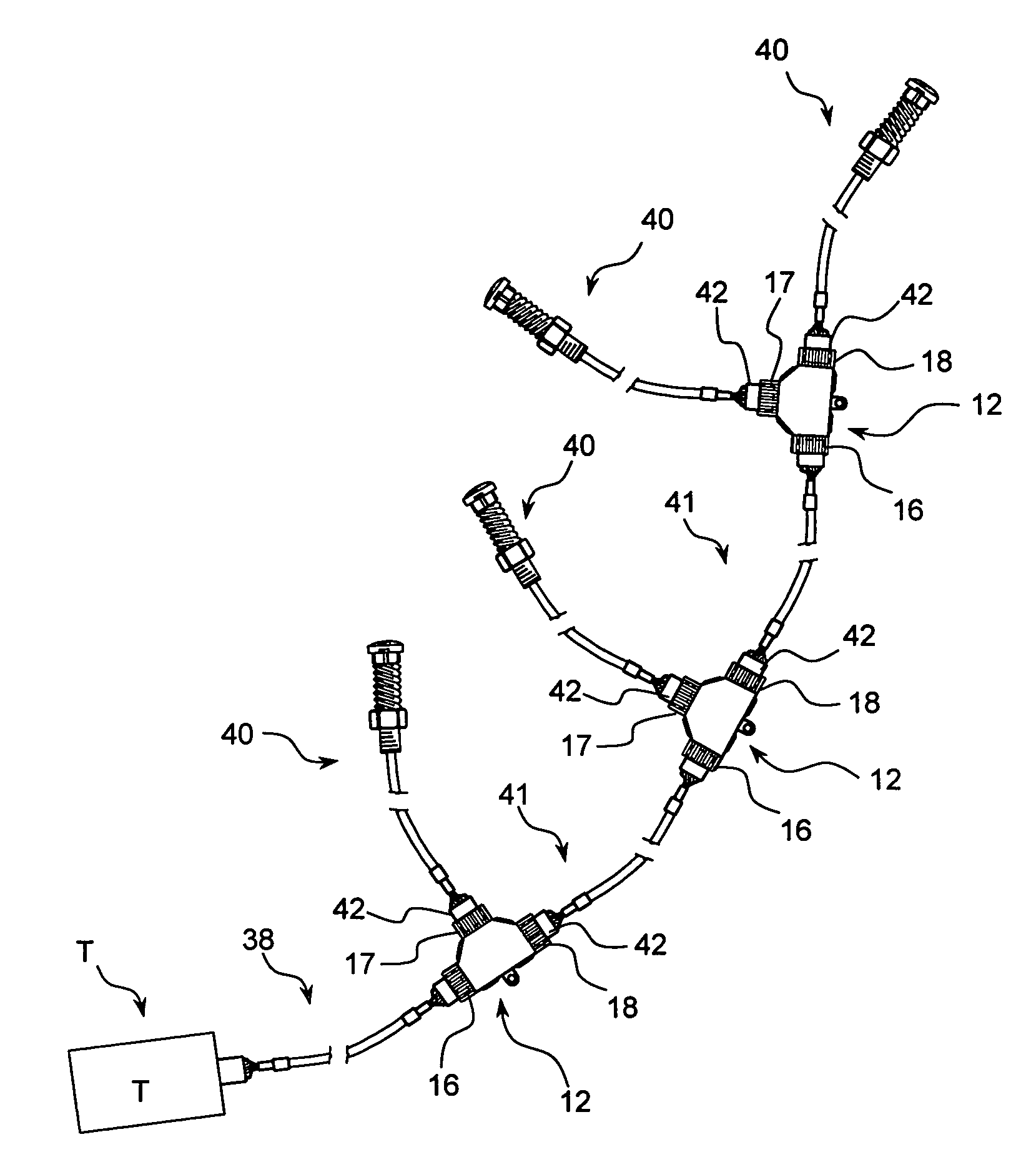
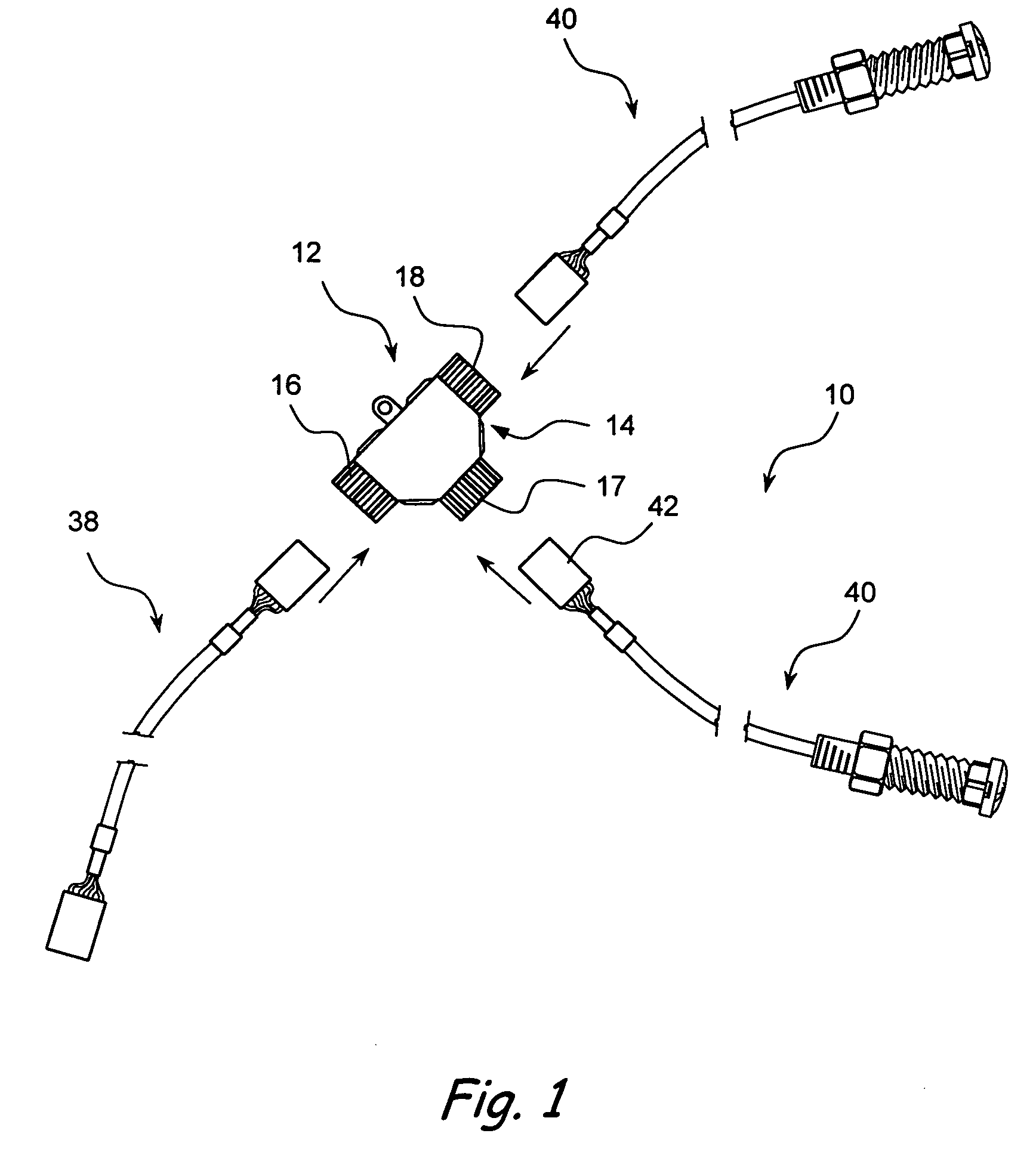
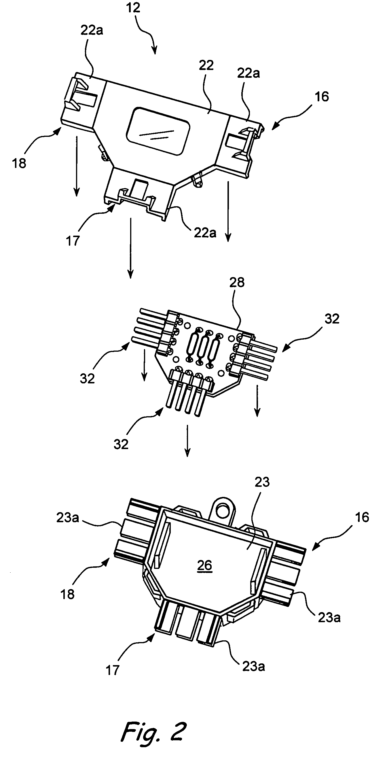
[0035]Referring now to FIG. 1, a system in accordance with the present invention is shown generally at 10. The system 10 generally comprises a junction hub 12 comprising a hub body 14 having a plurality of electrically connectors, for example, first, second and third connectors 16, 17, 18. Turning briefly to FIG. 2, the hub body 14 of the junction hub 12 is shown in exploded view. Hub body 14 may comprise first and second base portions 22, 23 which, when assembled, form a shallow cavity 26 containing a circuit board 28. Connectors 16, 17, 18 may be identical to one another. Connectors 16, 17, 18 are formed from protruding tabs portions 22a and 23a of base portions 22, 23 respectively, and contain electrically conductive prongs 32 of the circuit board 28.

[0036]Turning back now to FIG. 1, the first connector 16 is connectable to a signal transmission cable 38 that is effective to transmits a signal, for example, from a signal transmitter and / or a controller unit (not shown in FIG. 1) ...


PUM


Abstract

A surface-mounted lighting system and method wherein a lamp (e.g., an LED) is mounted within a surface (e.g., a wall, the wall of a pool or spa, a panel, etc.) such that it casts light to one side of the surface. A lighting system of the present invention comprises a) a lens cap/light emitting diode/first connector subassembly and b) a second connector/wire subassembly. A first connector located on the lens cap/light emitting diode/first connector subassembly is connectable to the second connector located on the second connector/wire subassembly such that power may be delivered through the second connector/wire subassembly to the lamp. Thereafter, when it is desired to remove or change the lamp, the first connector is disconnected from the second connector and the entire Lens cap/LED/first connector subassembly may be removed and replaced. In this manner, the lamp may be changed from a front or exposed side surface of a wall in which the lamp is mounted without the need to access wiring that is concealed or enclosed behind or on the opposite side of that wall.

Description

FIELD OF THE INVENTION[0001]The present invention relates generally to lighting systems and methods and more particularly to surface mounted lighting systems and methods that use light sources such as light emitting diodes (LEDs).BACKGROUND[0002]Various forms of lighting that use light emitting diodes (LED) light sources have recently been introduced. LEDs have a long life compared to other lamps, have a smaller physical form, operate on low voltage, are durable and allow digital addressing among other benefits. LEDs are primarily used in mobile appliances, signage, displays, architectural, transportation and consumer applications.[0003]LEDs with their unique attributes have been introduced in applications not possible with other lamps before. However, some of the unique attributes, in turn, contribute to shortcomings in some other areas. For instance, because of the small physical form, lamp replacement (LED replacement) may be difficult where the LED assemblies are in an enclosed,...

Claims


Application Information

Patent Timeline
IPC IPC(8): F21V33/00
CPCF21S2/00F21V19/001F21V19/04F21V19/042F21V23/06F21V33/004F21S8/024F21W2131/401F21Y2101/02H01R31/005F21W2121/02Y10S362/80F21Y2115/10
Inventor VAN DIEP, ALANJOHNSON, LAWRENCE MICHAEL
Owner HAYWARD IND INC
Why Eureka
Try Eureka