Serpentine wind turbine

a wind turbine and serpentine technology, applied in the field of wind turbines, can solve the problems of inefficient, dangerous, and serious consideration of a flexible tower, and reducing the effective swept area

Inactive Publication Date: 2003-09-09
SELSAM DOUGLAS SPRIGGS
View PDF10 Cites 128 Cited by
  • Summary
  • Abstract
  • Description
  • Claims
  • Application Information

AI Technical Summary

Problems solved by technology

The mass of such a large rotor, combined with the primitive state of technology of the day, precluded a serious consideration of a flexible tower.
Excessive bending deflection of the tower on these modern windmills is seen as sloppy, inefficient, and even dangerous.
The axis of rotation of the rotor is perpendicular to the tower, so excessive bending of the tower would tend to reduce the incident angle of the wind on the disk of the rotor, reducing the effective swept area.
With their hard mounting, the huge rotors and gargantuan machinery that supports them do not take kindly to being shaken about, due to stresses caused by inertial, vibrational, and coriolis type forces.
Often, at the price of aesthetic clutter and reduced utility of the land below, guy wires are used to further stabilize the rigid tower.
Current models, however, normally used for generating electricity, are still only barely feasible from an economic standpoint.
The rigid, vertical tower is often the most expensive component of a wind turbine.
Erection and even maintenance of such an unwieldy wind energy conversion system often requires a crane and other expensive equipment, to lift the heavy machine components to and from the top of the tower.
Deaths have resulted from accidents during these procedures.
Despite a general feeling among many designers that there "must be a better way", alternatives to the "standard model" have thus far proven not to be cost-effective.
Aside from the vertical axis designs, such as those of Darrieus, nobody is yet successfully thinking "out of the box" so to speak.
Designers have been as yet unable to break away from the traditional, basic, medieval design.
The decision to use a single large rotor, rather than many small rotors, is based on a desire for simplicity, and economy of scale, but results in a whole new series of expenses: First, the circular area subtended by a spinning rotor is proportional to the diameter squared, while the rotor's actual volume (and hence its mass), is proportional to the diameter cubed.
In the current state of the art, the increased complexity and consequent higher manufacturing and maintenance costs, as well as possible aesthetic clutter of such a multi-rotor technology, have weighed in favor of designs using a single large rotor, despite the disproportionately higher mass.
Also, the momentum and relative rigidity of a large, upwind rotor make it slow to accelerate, so the extra energy available in momentary or localized gusts is not fully utilized.
The wind-shadow reduces overall efficiency and can cause fatigue from stresses due to resonant vibrations induced by the repeated passage of the blades through the shadow.
B) the fact that the generator is often horizontally mounted at the top of the tower, and the electricity must be somehow transported to the ground; Over time, with no active yaw control, simple electrical cables are likely to eventually become twisted too far in one direction, so that slip rings must be used to transmit the electric power with rotational freedom.
Slip rings add complexity, and are not well-suited to larger installations.
For one, the aforementioned yaw control problem is nonexistent, since vertical axis turbines work equally well no matter what the direction of the wind.
The Darrieus type, for example, is not self-starting, and once started, does not collect as much energy, as smoothly, as an equivalent sized horizontal-axis rotor.
Such an installation may suffer from a large discrepancy in wind velocity between the tops and bottoms of its blades, since wind at ground level is markedly slowed by friction.
Guy wires can require an additional bearing at the top of the rotor, produce visual clutter, and reduce the agricultural or other viability of the land below.
A Savonius turbine has some of the advantages of the Darrius, being omnidirectional, and is self-starting, but unfortunately a Savonius is very inefficient.
Unfortunately, even this improved combination still swings a large, slow rotor, requiring a transmission to drive a faster-spinning generator, and utilizes a rigid, vertical tower at its core, with its inherent high cost.
Consequently a large rotor will turn a shaft at low rotational speed, but with high torque.
The gearbox required to achieve this increased rotational rate represents about 20% of the cost of current systems.
The weight of all this heavy-duty hardware must be supported by the rigid tower, further adding to the strength required of the tower, and its consequent cost.
The rigid, vertical towers in modern wind generation systems consume about another 20% of total system cost.
As you can see, current windmill designs result in a self-reinforcing cascade of upwardly spiraling costs.
More than one engineer has been frustrated that their best attempts to harness the light and fleet wind result in clanking, complicated, multi-ton monstrosities that literally shake themselves apart.
The challenge to wind energy development for the new millenium is to meet the wind on its own terms using the stronger, and more flexible materials now available.
If sufficiently strong, the presence of vertical axis type blades may even make a central shaft unnecessary.
Therefore, the use of smaller, multiple rotors further reduces the strength required of our tower / driveshaft.
This overcomes a well-recognized problem with larger, stiff, heavy rotors: due to their relative rigidity and high momentum, the energy of a localized gust cannot be efficiently harvested; The blades can't speed up fast enough to take full advantage of the extra energy in the momentary gust before it is too late and the gust has passed.
Since available power is proportional to wind velocity cubed, this can represent significant amounts of wasted energy.

Method used


Image

  • Serpentine wind turbine
  • Serpentine wind turbine
  • Serpentine wind turbine

Examples


first embodiment

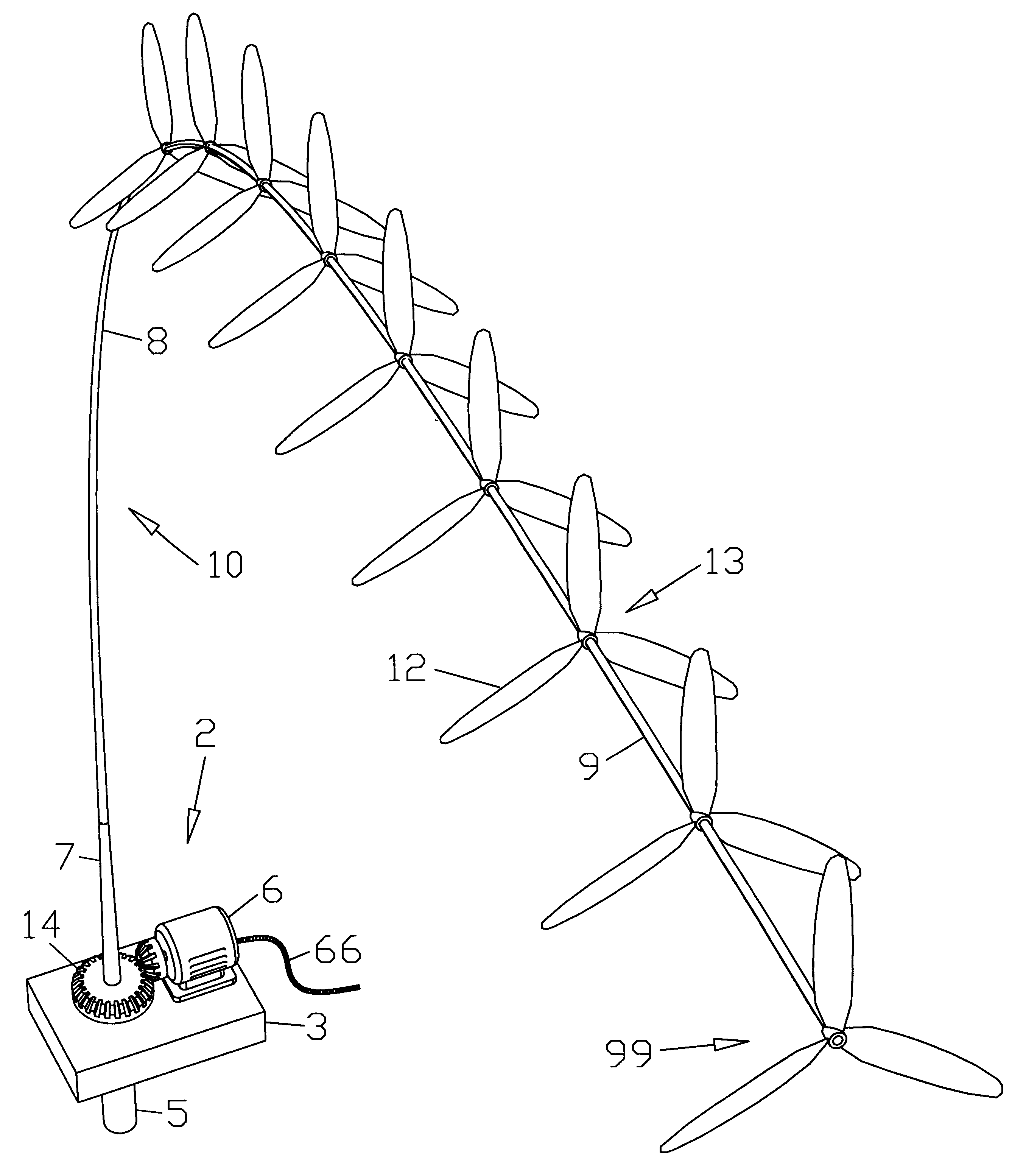
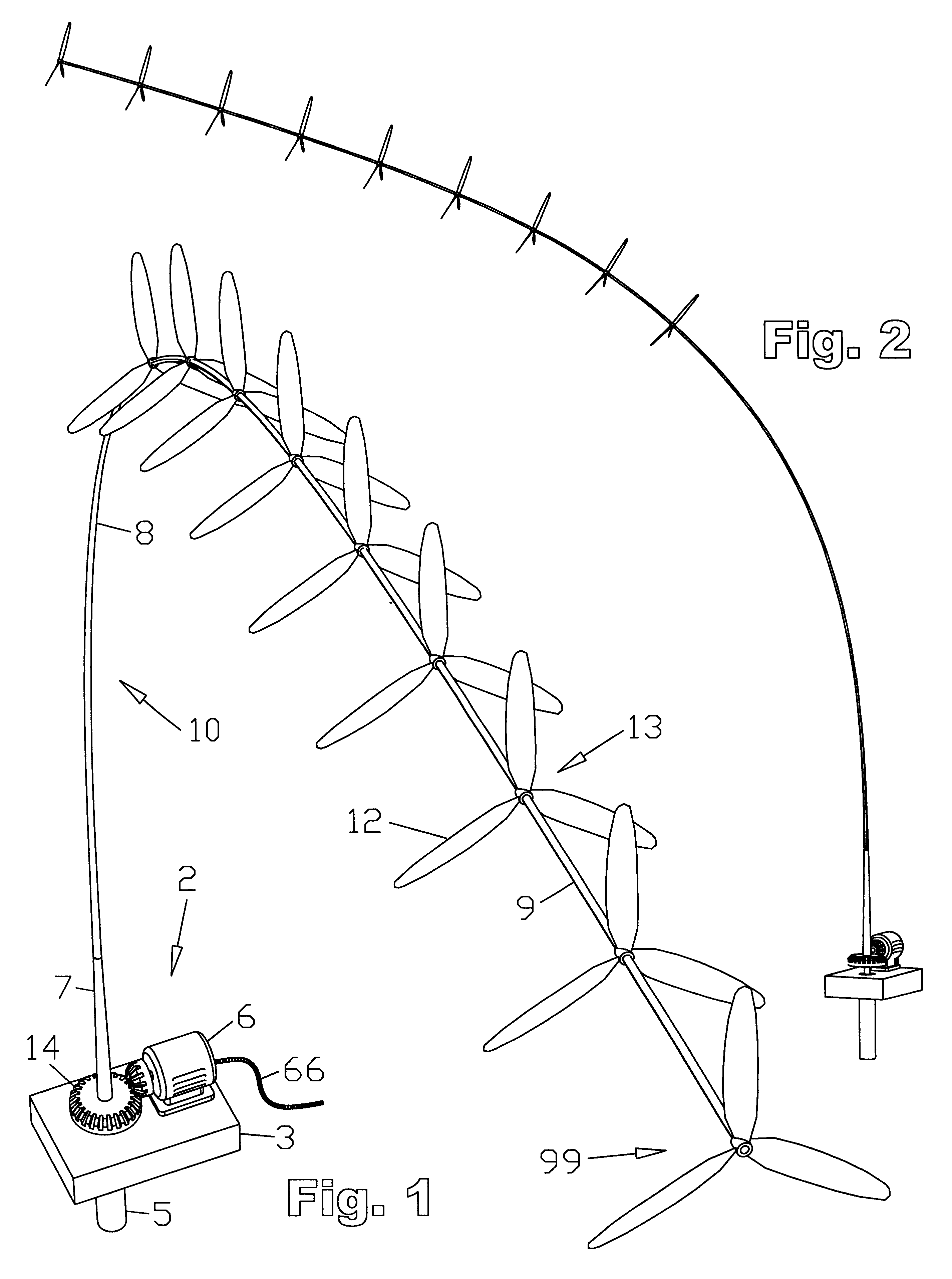
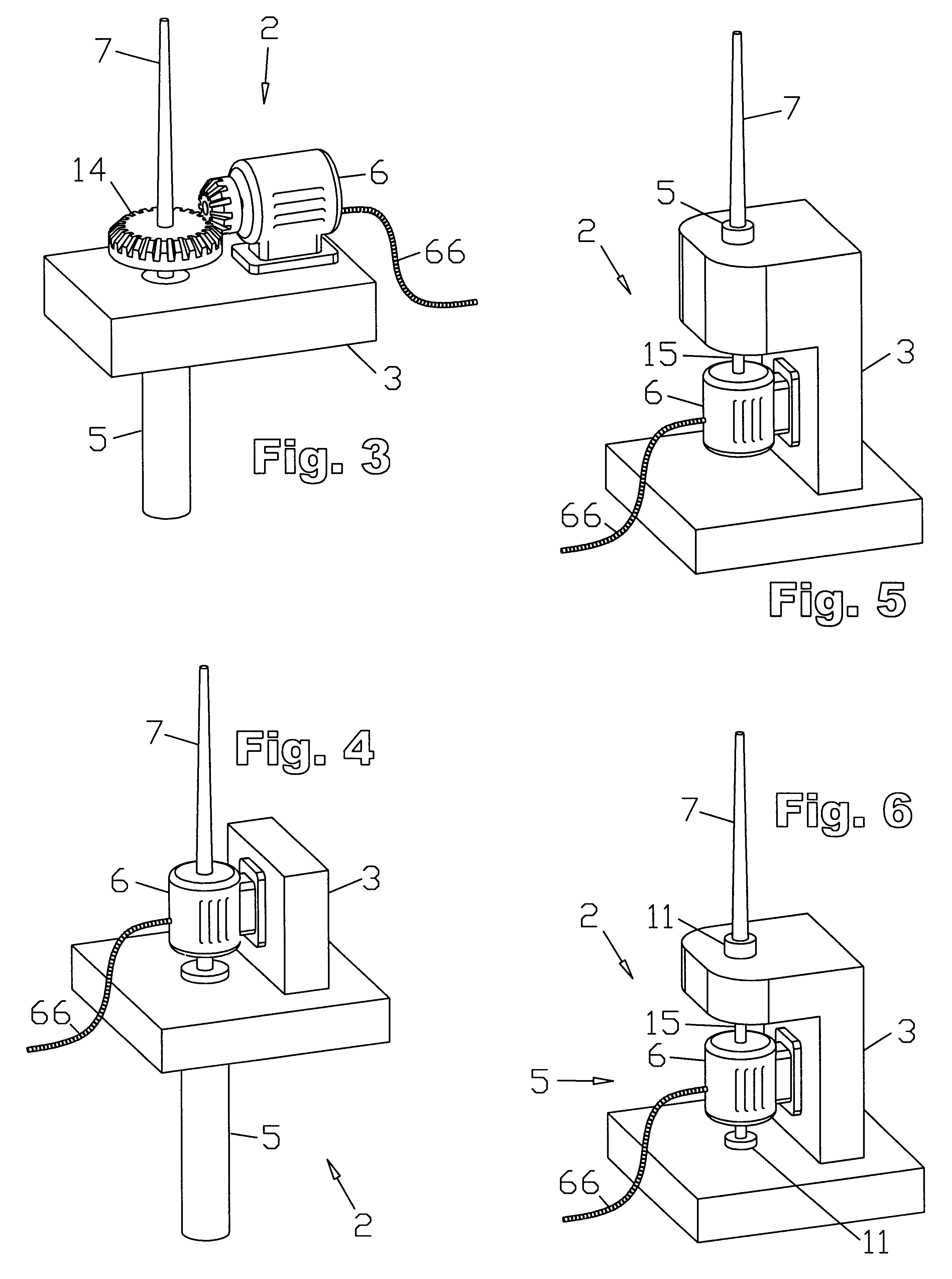
1. In the first embodiment, referring to FIGS. 1, 2, and 3, a rotating tower / driveshaft 10 comprising a resilient elongate structure, such as a flexible pole, that serves as both a tower and a driveshaft, extends substantially upward from a base means 2 located substantially at surface level. The base means 2, comprises a mounting means 3, a cantilevered bearing means 5, a power takeoff means 14, and a load 6. A closer cutaway view of such a base 2, as in FIG. 78, shows that the cantilevered bearing means 5 may comprise, for example, a substantially vertical axle 15, rotationally supported by two rotational bearing means 11, said bearing means 11 being located substantially proximate either end of said axle 15. Radial loads on the bearings can be substantially reduced by making the shaft 15 as long as is practical, thereby separating these bearings as far apart as is practical, so as to enhance their effective, combined leverage. The bearings are securely retained by a bearing suppo...

fifth embodiment

6. FIG. 9 shows an alternative subsurface base means similar to that of the fifth embodiment, in FIG. 8, except that the load 6 is disposed between the two rotational bearing means 11, as opposed to below them, taking up less overall space while maintaining the distance between the bearings 11. This particular base configuration was chosen for the sake of example only, to illustrate the wide variety of types of bases possible, within the overall scope of the invention, and need not necessarily be specifically associated with any particular rotor configuration.

7. FIG. 11 presents an alternative rotor blade configuration: three-bladed horizontal axis type rotors 13, sequentially offset by 60 degrees. (Due to symmetry, it would be equally accurate to say that they simply alternate in direction, and are therefore offset by 180 degrees.) The key concept here is that the rotors need not be perfectly aligned from one to the next. The rotors may be originally mounted in this offset way, or ...

eighth embodiment

9. In FIG. 13, single-bladed rotors project from the shaft in a helical pattern, at increments of 60 degrees. Such a configuration may encourage the entire tower / driveshaft to spin in a helical mode. The effect at any one point, as in the eighth embodiment, is that the rotor sweeps an enlarged arc, encountering more wind. One or more regions of stability, or harmonic nodes, having a more balanced rotor configuration, such as that of FIG. 10, may be combined on the same tower / driveshaft with a configuration such as this. One can quickly see that a wide variety of rotor configurations, combinations, and permutations thereof, are possible, within the scope of the present invention.

10. FIGS. 14 and 15 show a floating marine installation. Here the mounting means 3 is buoyant, being less dense than water, and floats at the surface 1 of a body of water. The bearing support means 4, here comprising a rigid hollow tube, extends below the water surface, being held down by the weight of ballas...


PUM


Abstract

Multiple horizontal axis type rotors are coaxially attached along the upper section of an elongate torque transmitting tower / driveshaft, The tower / driveshaft projects upward from a cantilevered bearing means, and is bent downwind, until the rotors become sufficiently aligned with the wind to rotate the entire tower / driveshaft, Power is drawn from the shaft at the base. Surface mount, subsurface mount, and marine installations, including a sailboat, are disclosed. Blade-to-blade lashing, and vertical axis rotor blades may also be included. Vertical and horizontal axis type rotor blades may be interconnected along the length of the tower / driveshaft to form a structural lattice, and the central shaft may even be eliminated. Aerodynamic lifting bodies or tails, buoyant lifting bodies, buoyant rotor blades, and methods of influencing the tilt of the rotors, can help elevate the structure. This wind turbine can have as few as one single moving part.

Description

1. Field of the InventionThis invention relates generally to the field of extracting usable energy from a moving fluid, more particularly to windmills.2. Prior ArtThe basic design of windmills, whether for grinding grain, pumping water, or generating electricity, has not significantly changed in hundreds of years. A stationary vertical tower supports a single upwind horizontal-axis rotor, which may drive a load either directly, or, more usually, through a mechanical transmission. The traditional windmill tower is rigid, with many historical examples actually being made of stone. A single large rotor served well on these early machines, since a large rotor spins slowly with high torque, perfect for turning a stone to grind grain. The mass of such a large rotor, combined with the primitive state of technology of the day, precluded a serious consideration of a flexible tower.Currently, the "single large rotor" design still prevails, despite the fact that today's electrical generators r...

Claims


Application Information

Patent Timeline
Patent Type & Authority Patents(United States)
IPC IPC(8): F03D11/04F03D1/00F03D1/02F03D11/00
CPCF03D1/025F03D11/04F05B2220/50F05B2240/921Y02E10/728F03D13/20F03D9/32F03D9/25Y02E10/72
Inventor SELSAM, DOUGLAS SPRIGGS
Owner SELSAM DOUGLAS SPRIGGS
Why Eureka
Try Eureka