Linear solid-state lighting with broad viewing angle

a solid-state lighting and broad viewing angle technology, applied in the field of linear led lamps, can solve problems such as the beam angle of 120°

Active Publication Date: 2011-07-21
ALEDDRA INC
View PDF7 Cites 133 Cited by
  • Summary
  • Abstract
  • Description
  • Claims
  • Application Information

AI Technical Summary

Benefits of technology

[0016]To protect consumers from possible electric shock during re-lamping, the present invention provides two special lamp bases, one for each end of the LLT lamp. Each lamp base contains a standard bi-pin and at least one shock protection switch, both mounted on a lamp base PCB, rather than on an end cover. This structure is different from that of the conventional LLT lamp, which uses two end caps in which the bi-pins are directly mounted.

Problems solved by technology

A conventional linear surface mount device (SMD) LED-based lamp can provide only a beam angle of 120° due to a limitation of Lambertian emitters.

Method used


Image

  • Linear solid-state lighting with broad viewing angle
  • Linear solid-state lighting with broad viewing angle
  • Linear solid-state lighting with broad viewing angle

Examples


Embodiment Construction

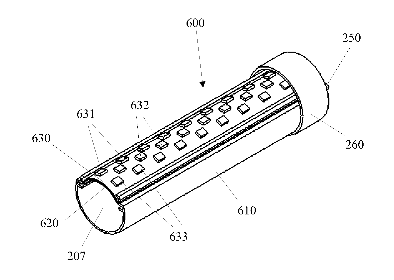
[0030]FIG. 4 is a cross-sectional view of the LLT lamp according to the present invention when the LED driver, the lamp base, and associated shock protection switches are omitted. The LLT lamp 600 has a housing 610 with a curved surface 620 on the top. The housing 610, preferably metallic in material, serves also as a heat sink with a toothed profile to increase the heat dispersion. Other types of projections can be formed on the outer surface of the housing for improved heat dispersion. On the top of the curved surface 620 is a thin and flexible single-piece LED PCB 630 curved to fit closely to the surface 620. The LED PCB 630 electrically and mechanically supports the SMD LEDs 631, 632, and 633, arranged in arrays. Because the LED PCB 630 follows the curvature of the surface 620 when it tightly fits on the surface 620, the SMD LEDs 631, 632, and 633 on the LED PCB 630 then have different normal directions relative to the tangential planes at their positions. Supposed that the angl...


PUM


Abstract

A linear light-emitting diode (LED)-based solid-state device comprising a curved surface to hold a flexible printed circuit board with multiple linear arrays of surface mount LEDs provides lighting applications with a broad viewing angle over 180° along the radial direction. On each of the two lamp bases of the lamp, a shock-protection switch is mounted to prevent shock hazard during re-lamping.

Description

BACKGROUND OF THE INVENTION[0001]1. Field of the Invention[0002]This invention relates to linear light-emitting diode (LED) lamps and more particularly to a linear LED lamp with a curved surface to provide a broad viewing angle over 180° along the radial direction.[0003]2. Description of the Related Art[0004]Solid-state lighting from semiconductor light-emitting diodes (LEDs) has received much attention in general lighting applications today. Because of its potential for more energy savings, better environmental protection (more eco-friendly, no mercury used, and no UV and infrared light emission), higher efficiency, smaller size, and much longer lifetime than conventional incandescent bulbs and fluorescent tubes, the LED-based solid-state lighting will be a mainstream for general lighting in the near future. Meanwhile, as LED technologies develop with the drive for energy efficiency and clean technologies worldwide, more families and organizations will adopt LED lighting for their ...

Claims


Application Information

Patent Timeline
Patent Type & Authority Applications(United States)
IPC IPC(8): F21V21/00H02H11/00
CPCF21V25/04F21Y2101/02F21K9/175F21Y2111/004F21Y2103/003F21K9/278F21Y2103/10F21Y2107/20F21Y2115/10
Inventor HSIA, CHUNGHOSHEN, PAI-SHENGLIN, CHING-FENG
Owner ALEDDRA INC
Why Eureka
Try Eureka