Maxillary arch expander unbanded to teeth

a maxillary arch and expander technology, applied in the field of orthodontic appliances, can solve the problem that the mouth pieces do not yet provide the lateral force to widen the jaw, and achieve the effect of expanding the jaw and reducing the size of the jaw

Active Publication Date: 2009-03-10
WILLIAMS MICHAEL O
View PDF10 Cites 105 Cited by
  • Summary
  • Abstract
  • Description
  • Claims
  • Application Information

AI Technical Summary

Problems solved by technology

The mouth pieces perform well to align teeth along an arc, however the mouth pieces do not yet provide expansive lateral forces to widen a jaw.

Method used


Image

  • Maxillary arch expander unbanded to teeth
  • Maxillary arch expander unbanded to teeth
  • Maxillary arch expander unbanded to teeth

Examples


Embodiment Construction

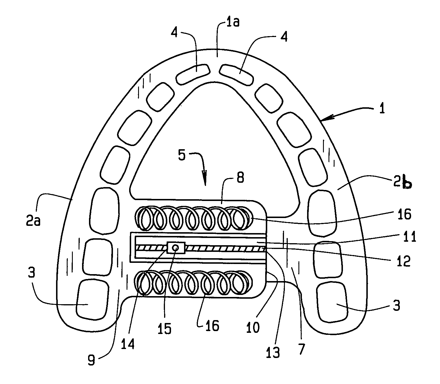
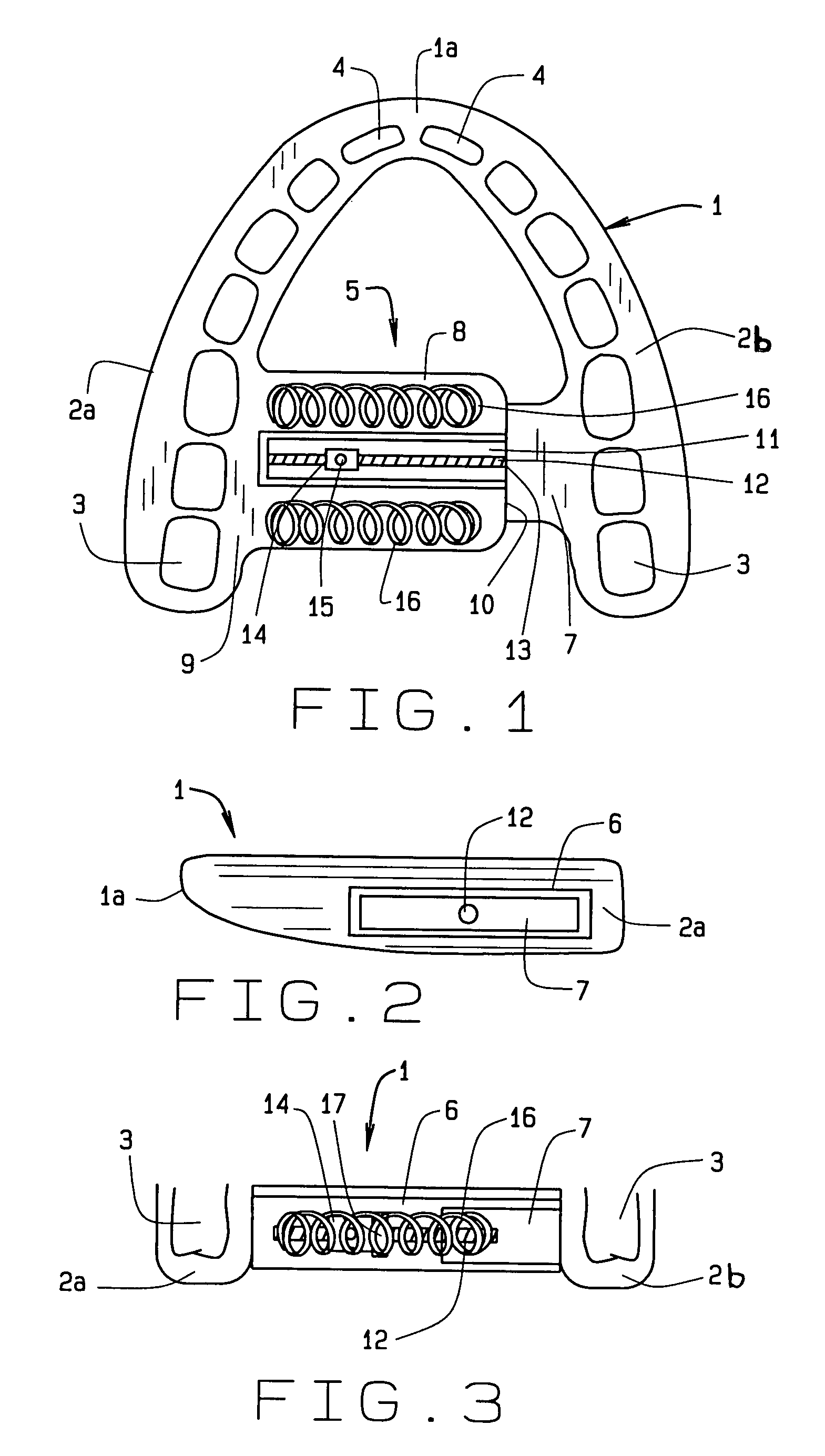
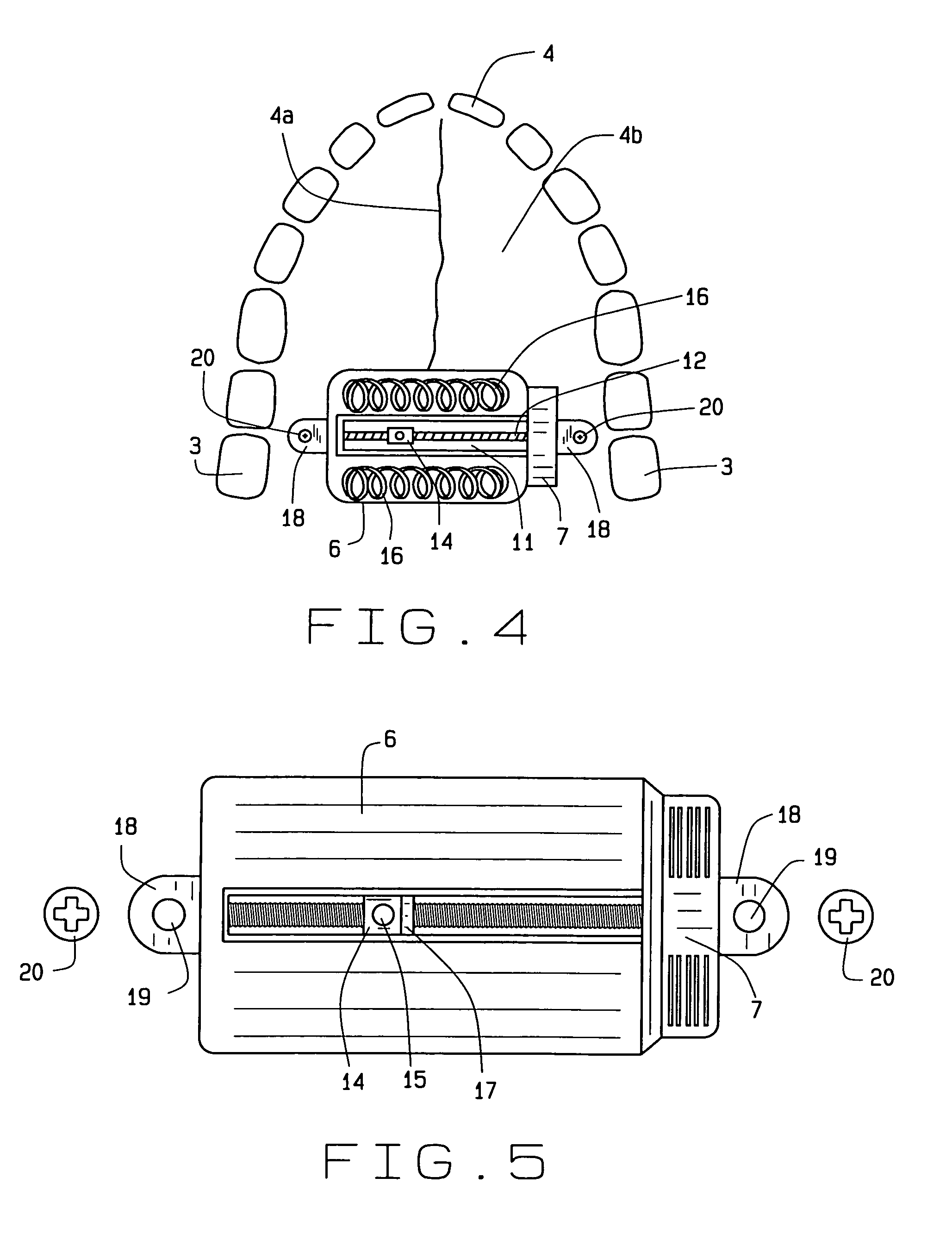
[0024]In referring to the drawings, FIG. 1 shows the present invention installed about the teeth of the upper or maxillary jaw of a person. The present invention comprises a mouthpiece 1 generally arcuate in shape made of a polymer material, often transparent. The mouthpiece has two wings 2, left 2a and right 2b, that join at the midpoint 1a of the mouthpiece. A wing begins where it fits over a molar 3 and then curves and narrows forward toward where it fits over an incisor 4. The mouthpiece fits snugly upon the outside of the teeth. The mouthpiece has preprogrammed features that contact the teeth to straighten them as done with the Invisalign® series of mouthpieces. The wings have a generally U shape in cross section that is sized to fit snugly upon the various teeth in the jaw. The wings are modeled with computer programs for precise fit and sizing. The mouthpiece using the wings straightens teeth and moves them into a desired arcuate form. However, the wings of existing mouthpiec...


PUM


Abstract

An orthodontic arch expander joins to a mouthpiece proximate to the rear of the mouthpiece. The transparent mouthpiece has a desired arc that fits over the teeth of the upper jaw. The mouthpiece has two wings that join near the incisors and then become parallel and spaced apart around the molars. Near the molars, an arch expander joins to the mouth piece. The arch expander has two telescoping shells with a threaded jack and cooperating springs. Each shell joins to a corresponding wing of the mouthpiece. Turning the jack lengthens a rod that pushes the shells outwards against the mouthpiece thus widening the maxillary arch without brackets or bands upon the teeth. An alternate embodiment has the arch expander attaching directly to the palatal bone through screws placed through a grommet at the end of each shell by an orthodontist or oral surgeon.

Description

CROSS REFERENCE TO RELATED APPLICATION[0001]This non-provisional application claims priority to the pending non-provisional application for patent Ser. No. 10 / 439,638, filed May 16, 2003, now U.S. Pat. No. 7,094,051, which is commonly owned by the same inventor, and which is a continuation-in-part of application Ser. No. 10 / 186,604, filed Jul. 2, 2002, now U.S. Pat. No. 6,877,982 which is a continuation-in-part of application Ser. No. 09 / 975,633, filed Oct. 12, 2001, now U.S. Pat. No. 6,719,557, which is a continuation-in-part of application Ser. No. 09 / 750,527, filed Dec. 29, 2000, now U.S. Pat. No. 6,520,772, which is a continuation-in-part of application Ser. No. 09 / 598,766, filed Jun. 22, 2000, now U.S. Pat. No. 6,402,510, which is a continuation-in-part of application Ser. No. 09 / 406,426, filed Sep. 27, 1999, now U.S. Pat. No. 6,241,517, which is a continuation-in-part of application Ser. No. 09 / 143,071, filed Aug. 28, 1998, now U.S. Pat. No. 6,036,488, which in turn is a conti...

Claims


Application Information

Patent Timeline
Patent Type & Authority Patents(United States)
IPC IPC(8): A61C3/00
CPCA61C7/10
Inventor WILLIAMS, MICHAEL O.
Owner WILLIAMS MICHAEL O
Why Eureka
Try Eureka