Flow control apparatus

a flow control and flow control technology, applied in mechanical devices, multiple way valves, transportation and packaging, etc., can solve the problems of unsatisfactory user adjustments, excessive consumption, and undesirable low-flow showerheads, so as to promote water conservation and quickly and easily adjust water flow.

Inactive Publication Date: 2009-03-17
SPEAKMAN
View PDF33 Cites 78 Cited by
  • Summary
  • Abstract
  • Description
  • Claims
  • Application Information

AI Technical Summary

Benefits of technology

[0007]An object of the invention is to promote the conservation of water during a shower by permitting a user to adjust the water flow to a low or no flow setting at times during a shower when a full flow is not needed.
[0009]Another object of the invention is to give the user the ability to quickly and easily adjust water flow during the shower.

Problems solved by technology

In a shower, the water is normally continuously running and results in excess consumption.
However, some users find these low-flow showerheads undesirable for many purposes, such as washing the hair, because of inadequate flow.
This requires multiple adjustments that would be equally troublesome to the user.
Second, if the water supply is shut off and turned on again after soaping, shampooing, or conditioning, the water temperature will probably be different and the water temperature must be readjusted, causing the person great inconvenience.
Accordingly, many people merely twist the showerhead to one side, thereby allowing water to flow continuously and causing water to be needlessly drained.

Method used


Image

  • Flow control apparatus
  • Flow control apparatus
  • Flow control apparatus

Examples


Embodiment Construction

[0030]The embodiments of the present invention will now be discussed. The particulars shown herein are by way of example and for illustrative discussion of the embodiments of the present invention. The embodiments are presented in the interest of providing what is considered to be a useful and readily understood description of the principles and conceptual aspects of the present invention. In this regard, a person of ordinary skill in the relevant art would recognize that other steps, configurations, arrangements or devices may be used to achieve the features of the invention without departing from the inventive concept and scope of the present invention. The description is presented, with the drawings, to only make apparent to those of ordinary skill in the art how some of the forms of the present invention may be embodied in practice.

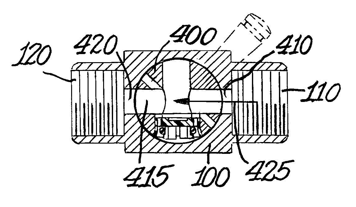
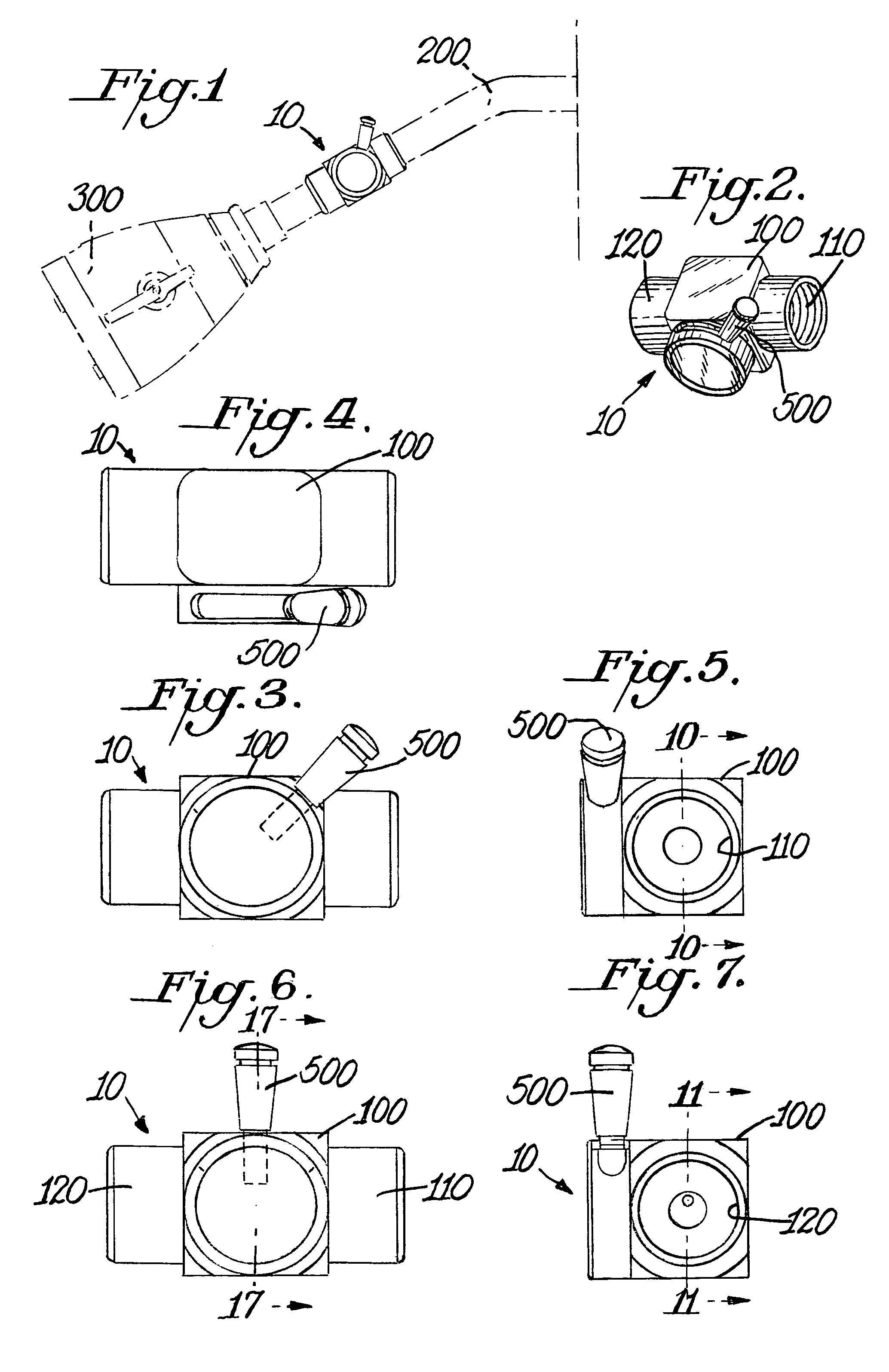
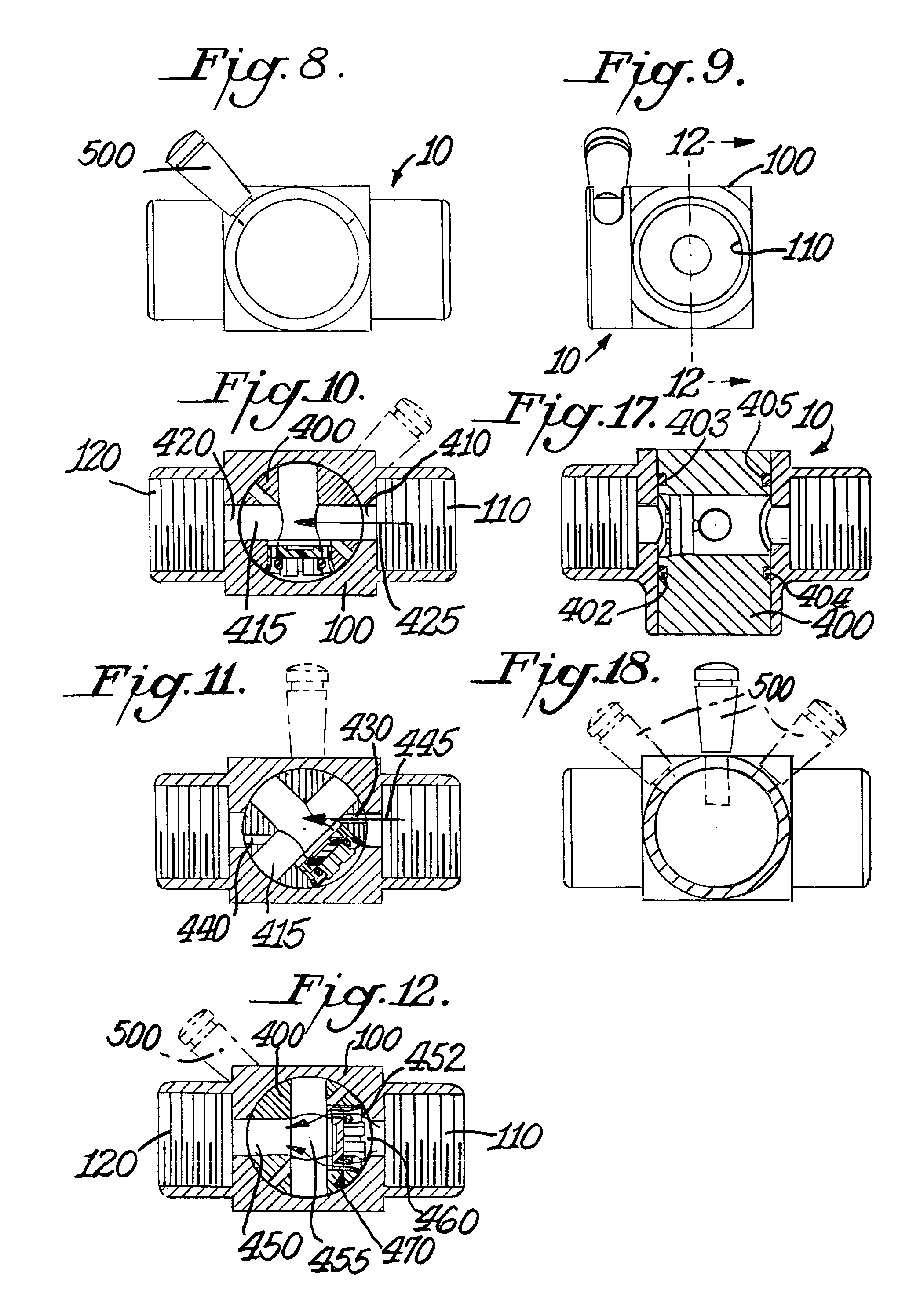
[0031]The flow controller of this invention is generally indicated at 10 in the figures. FIG. 1 illustrates flow controller 10 in one of its intended...


PUM


Abstract

The invention is a flow controller attachable to a water supply. The controller has a body with inlet and outlet connections and a control element positioned between the inlet and outlet. The controller has an actuator extending from the control element that permits selection of three different settings. The first setting aligns a set of openings in the control element with the inlet and outlet of the body permitting unimpeded full flow of water. A second setting aligns another set of openings, which form a weep hole, in the control element to substantially impede flow from the inlet to the outlet. A third setting aligns a third set of openings in the control element with a flow control device, to partially impede flow from the inlet to the outlet, creating a low flow.

Description

FIELD OF THE INVENTION[0001]This invention relates to an arrangement for selectively controlling fluid flow. More particularly, but not exclusively, the invention relates to the regulation of water flow for shower bath units.BACKGROUND OF THE INVENTION[0002]The use of a water flow control device for a shower is known in the prior art. Known prior art includes U.S. Pat. No. 6,474,621; U.S. Pat. No. 5,152,465; U.S. Pat. No. 5,123,628; U.S. Pat. No. 4,484,711; U.S. Pat. No. 4,398,668; U.S. Pat. No. 4,394,969; U.S. Pat. No. 4,273,289; U.S. Pat. No. 4,191,332; U.S. Pat. No. 3,547,353; and U.S. Pat. No. Des. 287,995. A myriad of regulations exist to conserve water by requiring devices to minimize consumption. Many of these water conservation devices focus of reducing the flow of water, i.e. low flow. The use of showers in personal hygiene is widespread in the United States and a pleasure to most users. Thus, showers provide a major opportunity in water conservation.[0003]In a shower, the ...

Claims


Application Information

Patent Timeline
Patent Type & Authority Patents(United States)
IPC IPC(8): F16K11/08E03C1/02
CPCF16K5/0407F16K11/0853Y10T137/86871
Inventor PATERSON, GRAHAM H.KAPPEL, FREDERICK M.
Owner SPEAKMAN
Why Eureka
Try Eureka