Automated flood irrigation system and method of using the same
What is AI technical title?
AI technical title is built by Patsnap AI team. It summarizes the technical point description of the patent document.
a flood irrigation system and automatic technology, applied in the field of automatic flood irrigation system, can solve the problems of unnecessary water run-off and labor-intensive, and achieve the effects of less labor-intensive, improved flood irrigation system efficiency, and improved water managemen
Active Publication Date: 2019-04-09
HILL THOMAS S
View PDF19 Cites 6 Cited by
Summary
Abstract
Description
Claims
Application Information
AI Technical Summary
This helps you quickly interpret patents by identifying the three key elements:
Problems solved by technology
Method used
Benefits of technology
Benefits of technology
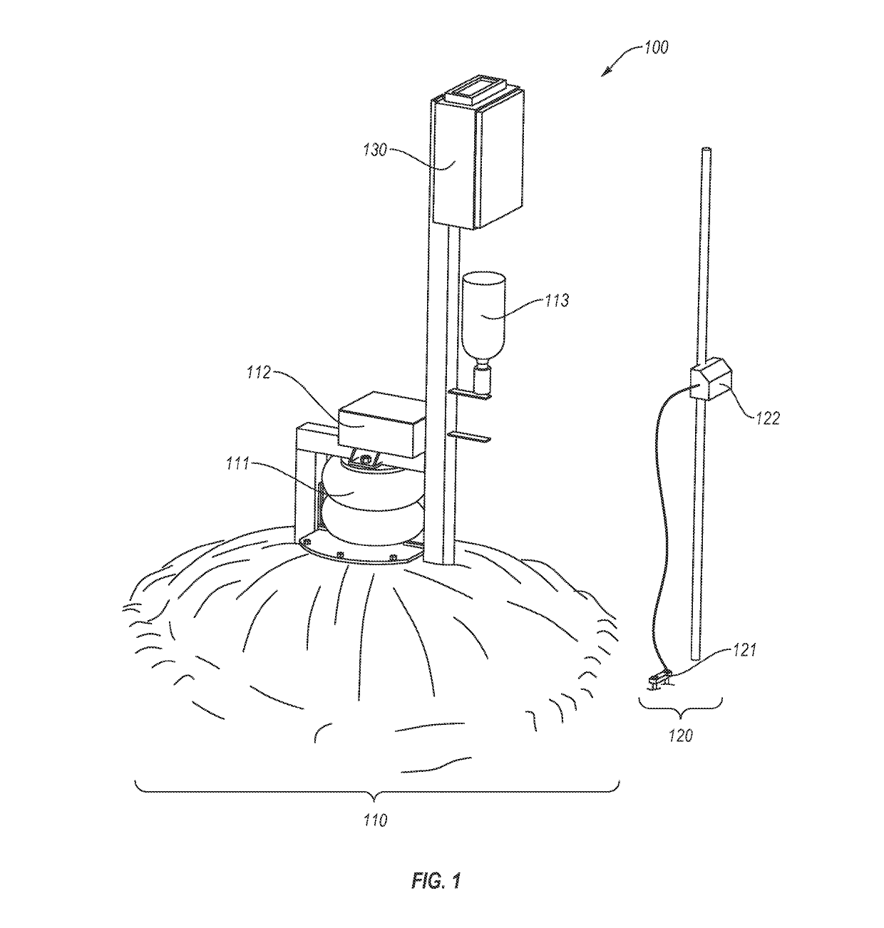
[0015]One advantage of an embodiment of the present invention is to promote the sustainability of water management on a worldwide scale. One deficiency with the related art is that they are very labor intensive and requires a paid employee to continuously check on the progress of water advancement for days at a time. The efficiency of a flood irrigation system may be improved by automating the surface irrigation process.
[0016]Another advantage of an embodiment of the present invention is to make the process of surface irrigation less labor intensive, and, as such, would cut costs and further promote the conservation of water. In the related art, risers are open and closed manually by unscrewing a lid or gate. As such, labor is required to release and to stop the release of water. Timing of the release and the stop release of the water may lead to unnecessary water run-off (e.g., due to a delay of closure of the lid to stop the release of the water after the surface has been irrigated). In an embodiment, this process will be made easier by allowing the user to open the water line at the push of a button. A sensor will be placed at the end of the field and will report back to the riser when the water has reached the end, signaling the riser to shut off. A networked flood irrigation system, consisting of a collection of risers and sensors, will further provide a stand-alone solution to the problem.
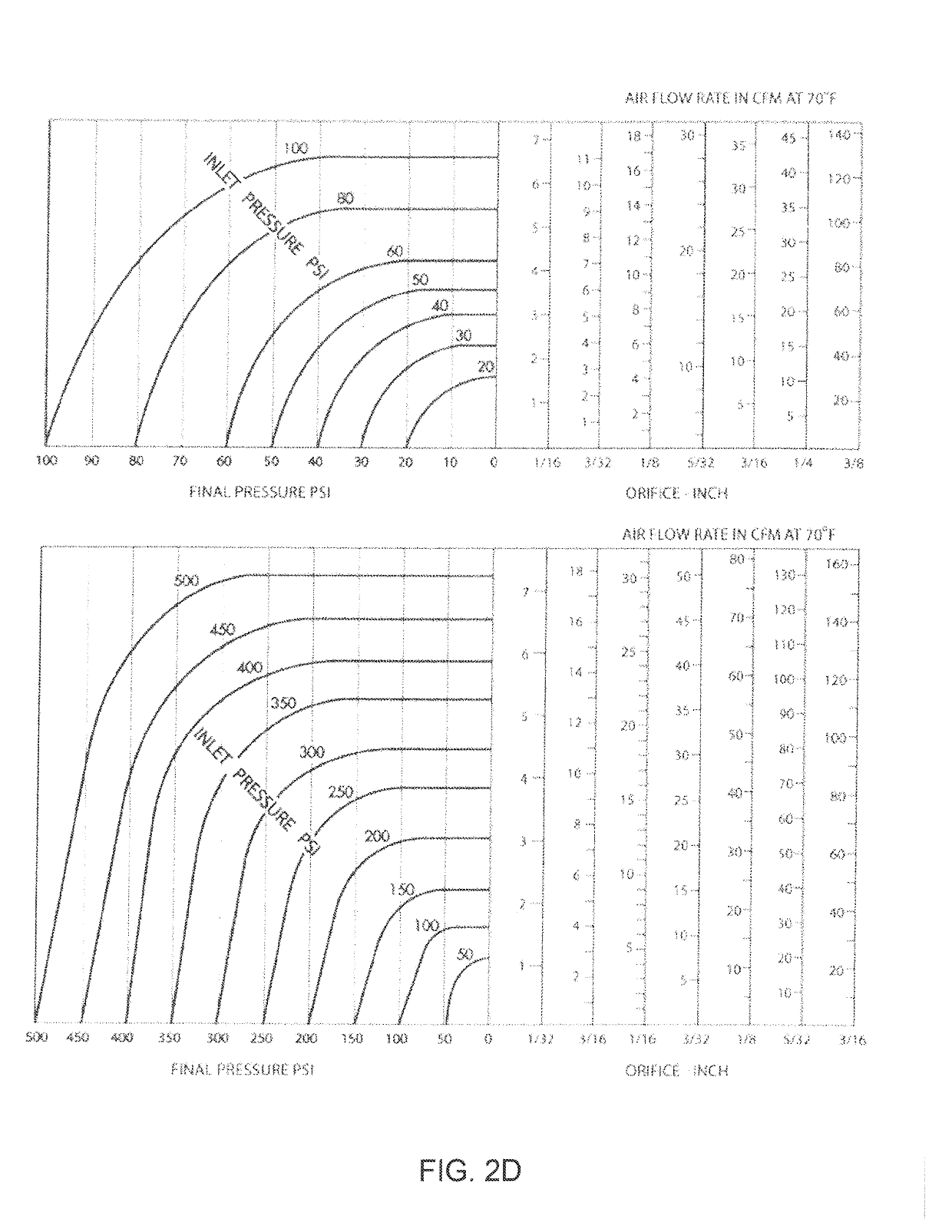
[0017]Yet another advantage of an embodiment of the present invention includes a control system for facilitating flood valve automation. This control system interprets signals from a wireless sensor node, and subsequently controls a flood valve. A gas powered air spring was chosen to open and close the valve. Mounted directly to the riser, and supplied with pressurized gas from a pressure vessel, the air spring controls the flow of water by inflating and deflating.
[0019]Another further advantage of an embodiment of the present invention is to provide an automated flood irrigation system that facilitates the conservation and equitable use of the water supply and to prevent unnecessary run-offs.
[0020]Another advantage of an embodiment of the present invention is to provide a system and method for automated flood irrigation that could modify and work with existing manual systems.
Problems solved by technology
One deficiency with the related art is that they are very labor intensive and requires a paid employee to continuously check on the progress of water advancement for days at a time.
Timing of the release and the stop release of the water may lead to unnecessary water run-off (e.g., due to a delay of closure of the lid to stop the release of the water after the surface has been irrigated).
Method used
Image
Click on the blue label to locate the original text in one second.
Reading with bidirectional positioning of images and text.
Examples
examples
[0144]Without intending to limit the scope of the invention, the following examples illustrate how various embodiments of the invention may be implemented in various applications.
[0145]There is interest in developing and implementing irrigation methods that contribute to sustainable farming practices, especially in the areas of producing alfalfa, alfalfa seed, and cereal grains using flood irrigation.
[0146]Currently, the flood irrigation industry pays individuals to manually flood fields; this method can take up to 12 hours of paid labor. An automated flood irrigation system is design to eliminate labor and maximize efficiency.
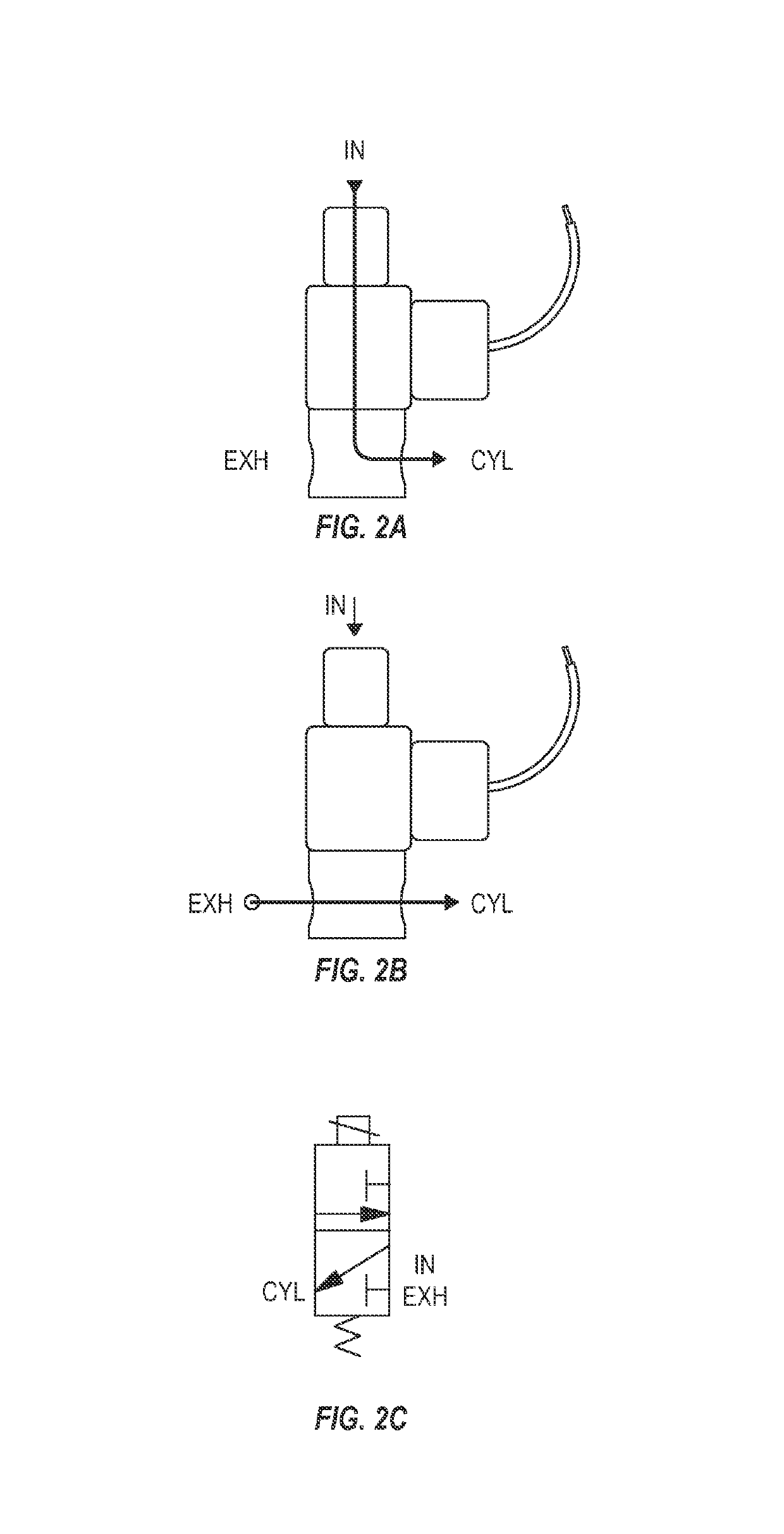
[0147]FIG. 8 illustrates an exemplary exploded view of a riser assembly of a flood irrigation system according to an embodiment.
[0148]Referring to FIG. 8, the riser assembly includes a lower riser alfalfa valve adaptor 801, a lid assembly 802, an air spring 803 (e.g., by McMaser-Carr), a support structure 804, a gas control box 805 (e.g., by Digi Key), a gas a...
PUM
Abstract
A method for flood irrigation includes releasing water from a riser valve for flooding a portion of a field through a control of a corresponding riser device of a plurality of riser devices, wherein the corresponding riser device is deployed at a location proximate to the riser valve, receiving a wireless signal from a corresponding sensor device of a plurality of sensor devices for a detection of a flood condition, wherein the corresponding sensor device is deployed at a location proximate to where the water from the riser valve is expected to flood; and stopping the release of the water from the riser valve.
Description
CROSS REFERENCE TO RELATED APPLICATION[0001]The present application is claims the benefits of and priority, under 35 U.S.C. § 119(e), to U.S. Provisional Application Ser. No. 62 / 037,960, filed Aug. 15, 2014; the above-identified application being fully incorporated herein by reference.COMPUTER PROGRAM LISTING APPENDIX[0002]A computer program listing appendix containing the source code of computer programs that may be used with the present invention is incorporated by reference in its entirety and appended to this application as one (1) original compact disc, and one (1) identical copy thereof, containing a total of twenty-four (24) files as follows:[0003]FilenameSize (bytes)Date of CreationRiser_1.ino8,813Apr. 15, 2015Riser_2.ino9,016Apr. 15, 2015Riser_3.ino9,016Apr. 15, 2015Riser_4.ino9,016Apr. 15, 2015Riser_5.ino9,016Apr. 15, 2015Riser_6.ino9,016Apr. 15, 2015Riser_7.ino9,016Apr. 15, 2015Riser_8.ino9,016Apr. 15, 2015Riser_9.ino9,017Apr. 15, 2015Riser_10.ino9,019Apr. 15, 2015Riser_1...
Claims
Application Information
Patent Timeline
Application Date:The date an application was filed.
Publication Date:The date a patent or application was officially published.
First Publication Date:The earliest publication date of a patent with the same application number.
Issue Date:Publication date of the patent grant document.
PCT Entry Date:The Entry date of PCT National Phase.
Estimated Expiry Date:The statutory expiry date of a patent right according to the Patent Law, and it is the longest term of protection that the patent right can achieve without the termination of the patent right due to other reasons(Term extension factor has been taken into account ).
Invalid Date:Actual expiry date is based on effective date or publication date of legal transaction data of invalid patent.

