Portable container assembly

a container and assembly technology, applied in the field of containers, can solve the problem that the worker's needs to bring to the work place cannot be fully accommodated

Active Publication Date: 2009-03-17
KETER PLASTIC LTD
View PDF19 Cites 92 Cited by
  • Summary
  • Abstract
  • Description
  • Claims
  • Application Information

AI Technical Summary

Benefits of technology

[0023]For easy displacement of the cabinet assembly into its tilted rolling position, there is formed, adjacent a bottom end of the base cabinet, a footstep portion for an individual to step on when tilting the assembly.

Problems solved by technology

But more often than not, what the worker needs to bring to the work place cannot be fully accommodated even in an exceptionally large-capacity tool box.

Method used


Image

  • Portable container assembly
  • Portable container assembly
  • Portable container assembly

Examples


Embodiment Construction

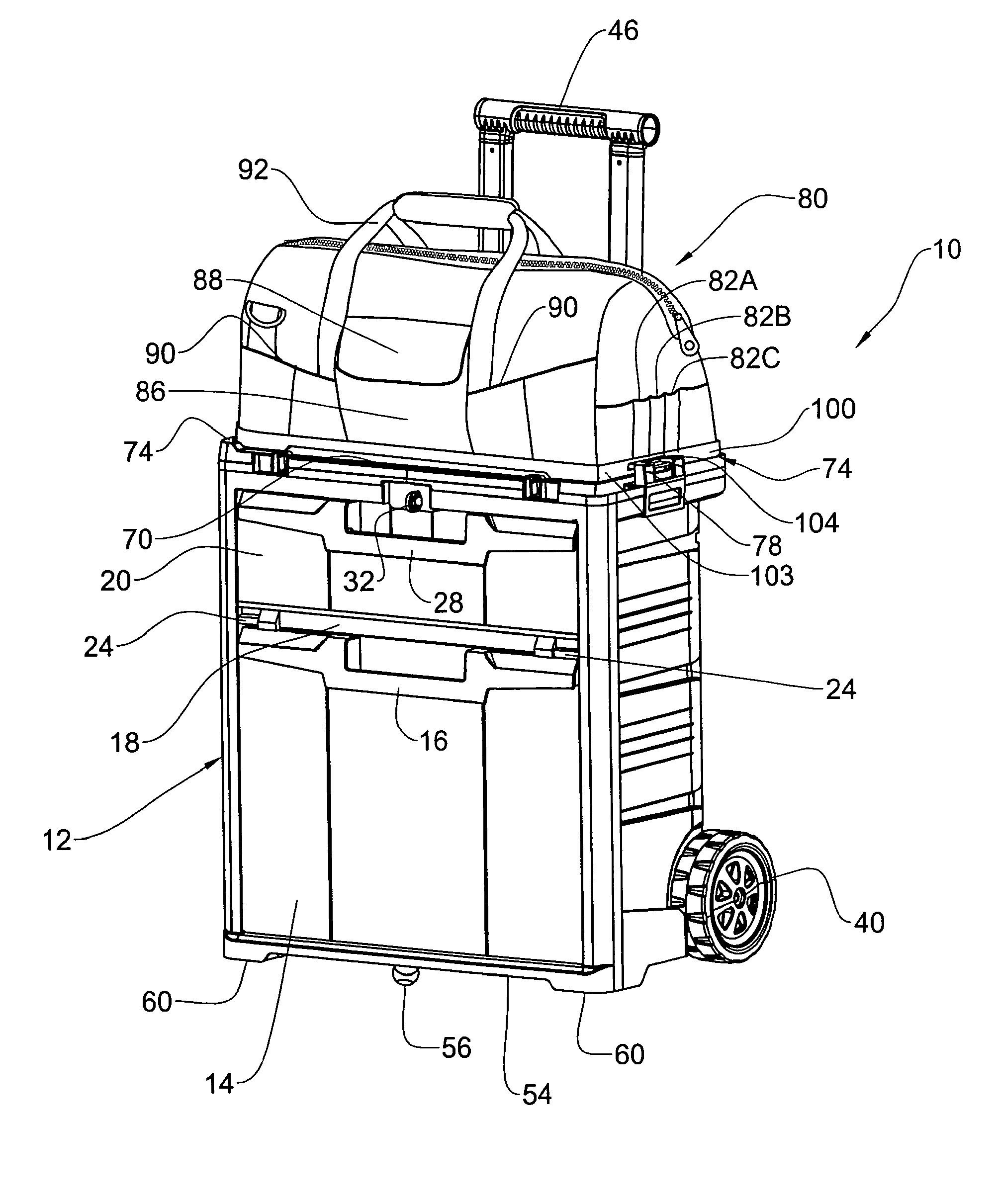
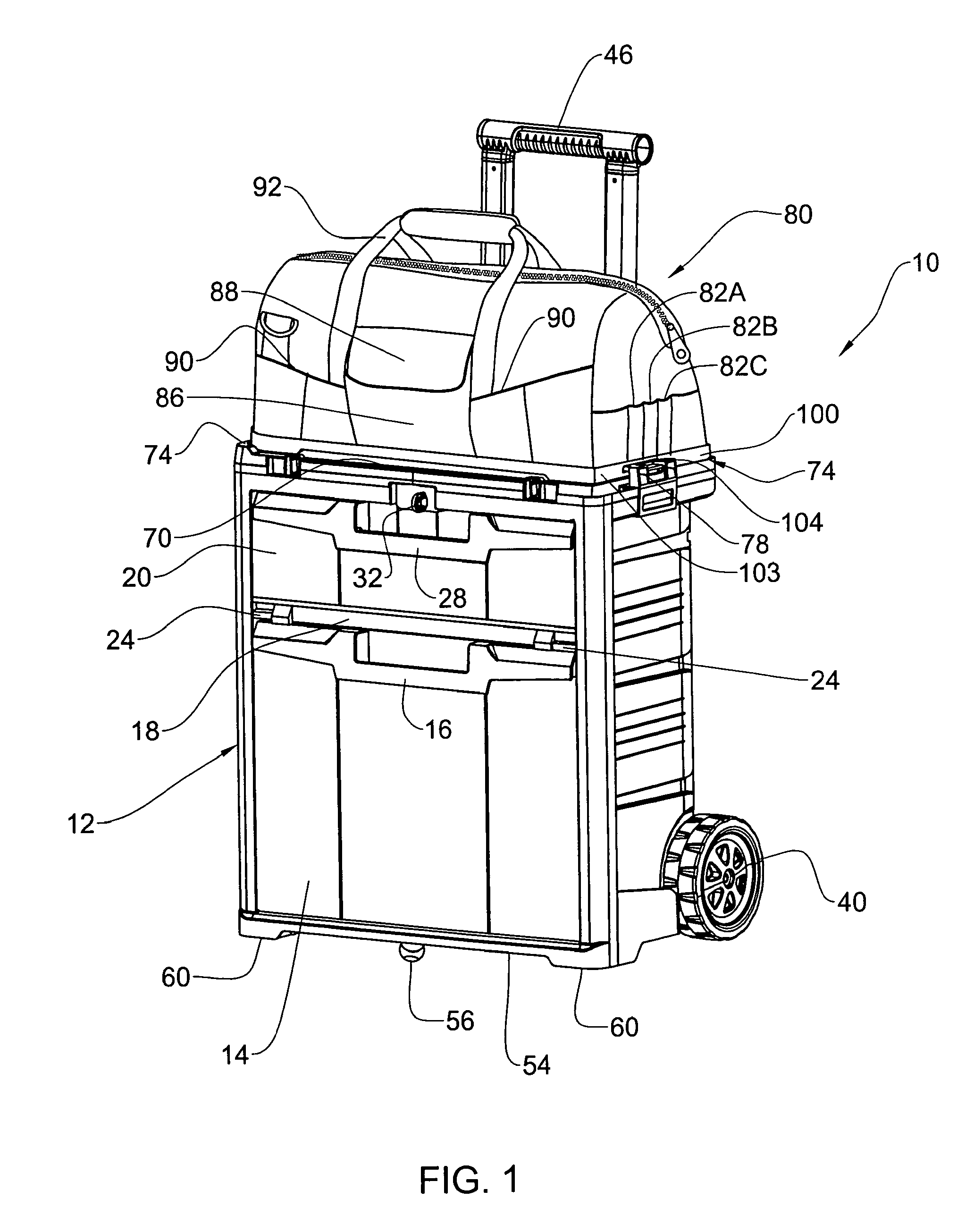
[0036]Attention is first directed to FIG. 1 of the drawings illustrating a cabinet assembly in accordance with the first embodiment of the present invention generally designated 10, comprising a rigid base cabinet 12 fitted with a tilting bin 14 accessible by pulling at handle 16 in a pivoting manner. Above the bin 14 there is a fixed shelf 18 giving rise to a storage compartment closable by a door 20 pivotally secured at 24 to the base cabinet. Door 20 is fitted with a handle 28 and an opening through which projects a locking eye 32, for a lock to be mounted, to thereby lock the compartment 18 and prevent unauthorized opening thereof.

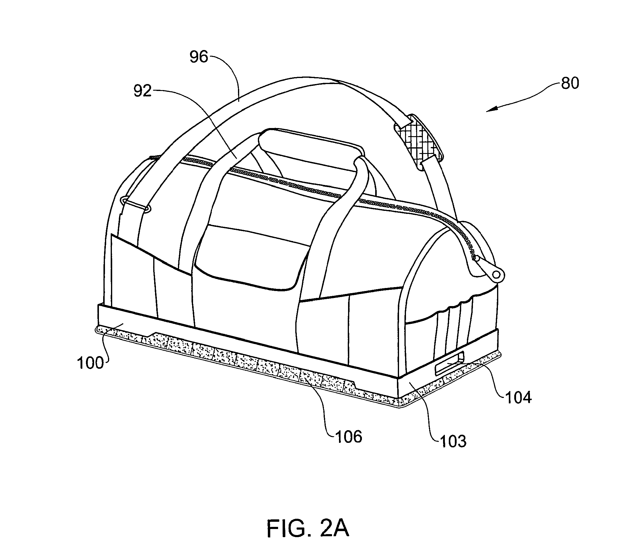
[0037]As can further be seen in FIGS. 1 and 2B, the base cabinet 12 comprises a pair of wheels 40 (only one seen in FIG. 1) fitted at a rear lower end of the base cabinet so as to facilitate locomoting the cabinet assembly by pulling at handle 46. As can be seen also in FIG. 2B, the handle 46 is in the form of a telescopic handle with two retractable b...


PUM


Abstract

A wheeled cabinet assembly comprising a wheeled base cabinet fitted with a locomoting handle, and at least one detachable container made from a pliable material and designed as an independent carrying bag wherein a base portion of the carrying bag is attachable over a top edge of the base cabinet at an upright position or at a bottoms up position.

Description

[0001]This application claims the benefit of prior U.S. provisional patent application No. 60 / 681,159 filed May 16, 2005, the contents of which are hereby incorporated by reference in their entirety.FIELD OF THE INVENTION[0002]This invention relates generally to containers adapted to store any items a person may require such as hobby gear (fishing equipment, remote controlled items, etc), tools, nuts and bolts, and whatever other articles a worker requires to perform various tasks at a workplace, and more particularly to a portable container assembly which can be wheeled to a workplace.[0003]Whilst hereinafter in the specification and claims the assembly is referred to as a tool assembly, it should be understood in its broad meaning, namely suited for any type of equipment and gear.BACKGROUND OF THE INVENTION[0004]When a mechanic works in a garage to repair automobiles, the tools, the gauges, the bolts and all other articles he may require for this purpose are then available to the ...

Claims


Application Information

Patent Timeline
Patent Type & Authority Patents(United States)
IPC IPC(8): B62B1/04
CPCA45C7/0045B25H3/00B25H3/023B25H3/026
Inventor DUVIGNEAU, NIKOLAI
Owner KETER PLASTIC LTD
Why Eureka
Try Eureka