This technology while theoretically possible is operationally difficult to hit such a small underground target, i.e the axial cross-section of a typical 8-inch wellbore using a horizontal penetrating
drill bit.
This type of downhole
flange connection is extremely difficult if not impossible to implement in current oilfield practice.
The laboratory demonstration in this patent shows that the annular steam zone is very conductive to
oil production and allows premature steam breakthrough.
Based on this demonstrated observation, it is difficult if not impossible, to conceive a situation taught by this patent in which the injected steam as drive fluid will not preferentially flow under the hundreds of pounds
injection pressure along the heated annular zone and thus bypassing the cold
viscous oil saturated formation.
It is difficult to visualize the steam entering a cold highly viscous formation while a highly open wellbore is available for fluid flow away from the formation.
This situation is not only physically impossible but it thermodynamically impossible for the hot fluid to flow “against the pressure gradient”.
Very few of these prior art systems have been used in the industry with any success because of their technical complexity, operational difficulties, and being physically impossible to implement or being extremely uneconomical systems.
These include; the inability of the method to inject the hot fluid into a cold highly
viscous oil in the formation; the inability to overcome the
viscosity effect, wherein the
viscosity of steam is less than 0.020 cp under the reservoir conditions which makes the flow of steam through porous media 5,000,000 times easier than cold high
viscosity oil of 100,000 cp.
This
flow ratio is based directly on the viscosity ratios of 100,000 / 0.02; the inability of the method or process to prevent bypass of injected fluid directly from the
injector source towards the producing sink; the inability of the method or process to provide an effective seal to prevent
high pressure injected steam from bypassing cold
viscous oil impregnated formation and moving directly from the
injector source towards the producing sink; the inability of the method or process to form a viable communication zone from the steam zone or chamber to the producing sink while preventing bypass and early breakthrough of steam; the inability of the process to utilize the significant
gravity drainage effects created by the
low density of the hot steam compared to
condensed water and hot oil; the inability of the method to heat the formation effectively by physical contact between the steam and the rock formation such that the
latent heat, which the major source of
heat energy compared to the
sensible heat, can be transferred to the rock and hydrocarbons efficiently; the requirement of long injection lead times of months to years of hot
fluid injection, before there is any production response of the displaced oil; the use of overly complex equipment of questionable
operational effectiveness to implement the method in the field.
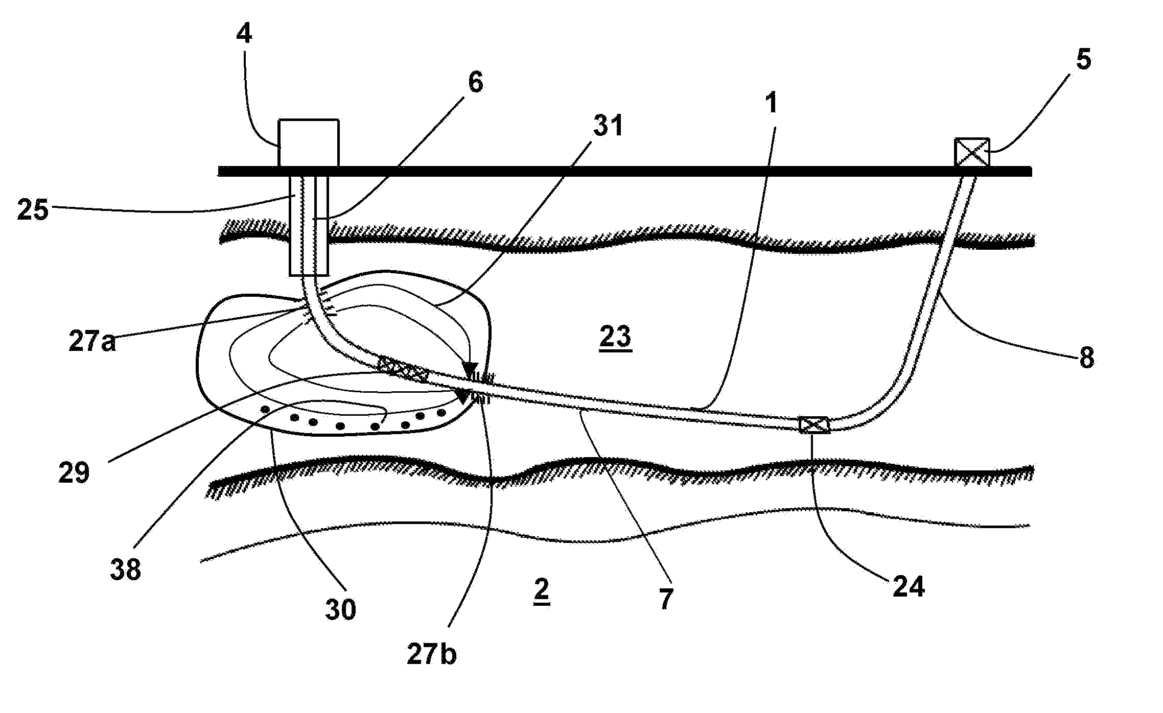
Secondly, the
large distance between the top of the formation and the bottom of the formation will cause condensation of the drive steam allowing essentially hot water to be produced at the bottom with low quality steam, both fluids being re-circulated back to the surface.
In addition the mechanism to heat the near wellbore can only be based on conductive
heat transfer through the steel casing.
Since there is
no formation rock contact with the steam fluid in which
latent heat transfer to formation fluids and rock is the major heat
transport system, the U.S. Pat. No. 3,994,341 method is incapable of delivering sufficient heat in a reasonable time to heat the formation sufficiently lower the viscosity of the oil, raise the
porosity and permeability of the formation as taught in the present
patent application.
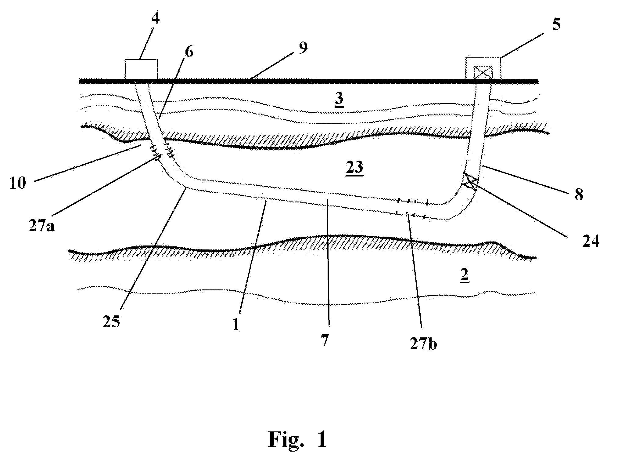
To date, the majority of producing or injection horizontal well embodiments shown in the
petroleum industry have but a single
wellhead and are all limited by several physical and operational problems associated with the physical nature of the embodiments.
No effort to date has used this technology effectively for oil
recovery in a manner and form such as the uniwell™ described herein.
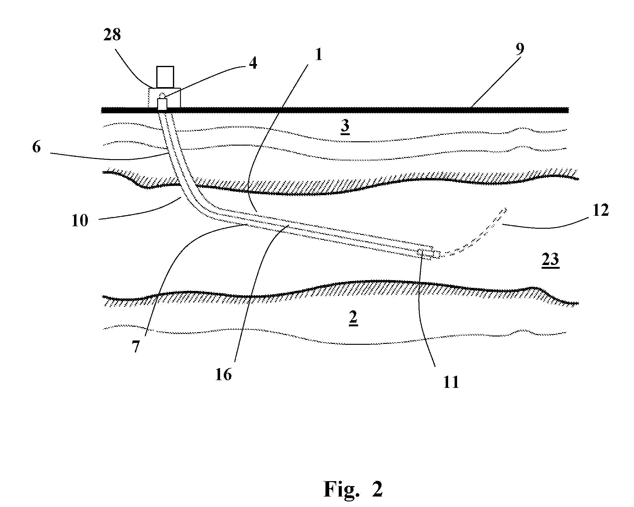
This problem has continued to baffle the contemporary and prior art with possibly the only exception being the SAGD patent which uses two
horizontal wells closely juxtaposed in a
vertical plane.
Even this SAGD approach has inherent difficulties in initiating the hot oil flow between the two wellbores.

