Method and device for monitoring blind spots of a motor vehicle

a technology for motor vehicles and blind spots, applied in the direction of instruments, pedestrian/occupant safety arrangements, and reradiation, etc., can solve the problems of not being able to examine the side of the vehicle that the driver is not able to examine without a significant change in the field, and the driver is not able to examine all the regions

Active Publication Date: 2009-03-17
VOLKSWAGEN AG
View PDF17 Cites 17 Cited by
  • Summary
  • Abstract
  • Description
  • Claims
  • Application Information

AI Technical Summary

Problems solved by technology

Because of the restricted field of view of the driver and the geometrical relationships in a vehicle, that is, for example, because of posts between the vehicle's windows that hinder vision, it is generally not possible for the driver of the vehicle to examine all the regions around a vehicle without turning around or turning the head.
Directly behind and in front of the vehicle there are regions that the driver is not able to examine.
Similarly, there are regions at the side of the vehicle that the driver is not able to examine without a considerable change in the field of vision by turning his head.
A disadvantage is that object may be pointed out to the driver that are meaningless for the guidance of the vehicle.

Method used


Image

  • Method and device for monitoring blind spots of a motor vehicle
  • Method and device for monitoring blind spots of a motor vehicle
  • Method and device for monitoring blind spots of a motor vehicle

Examples


Embodiment Construction

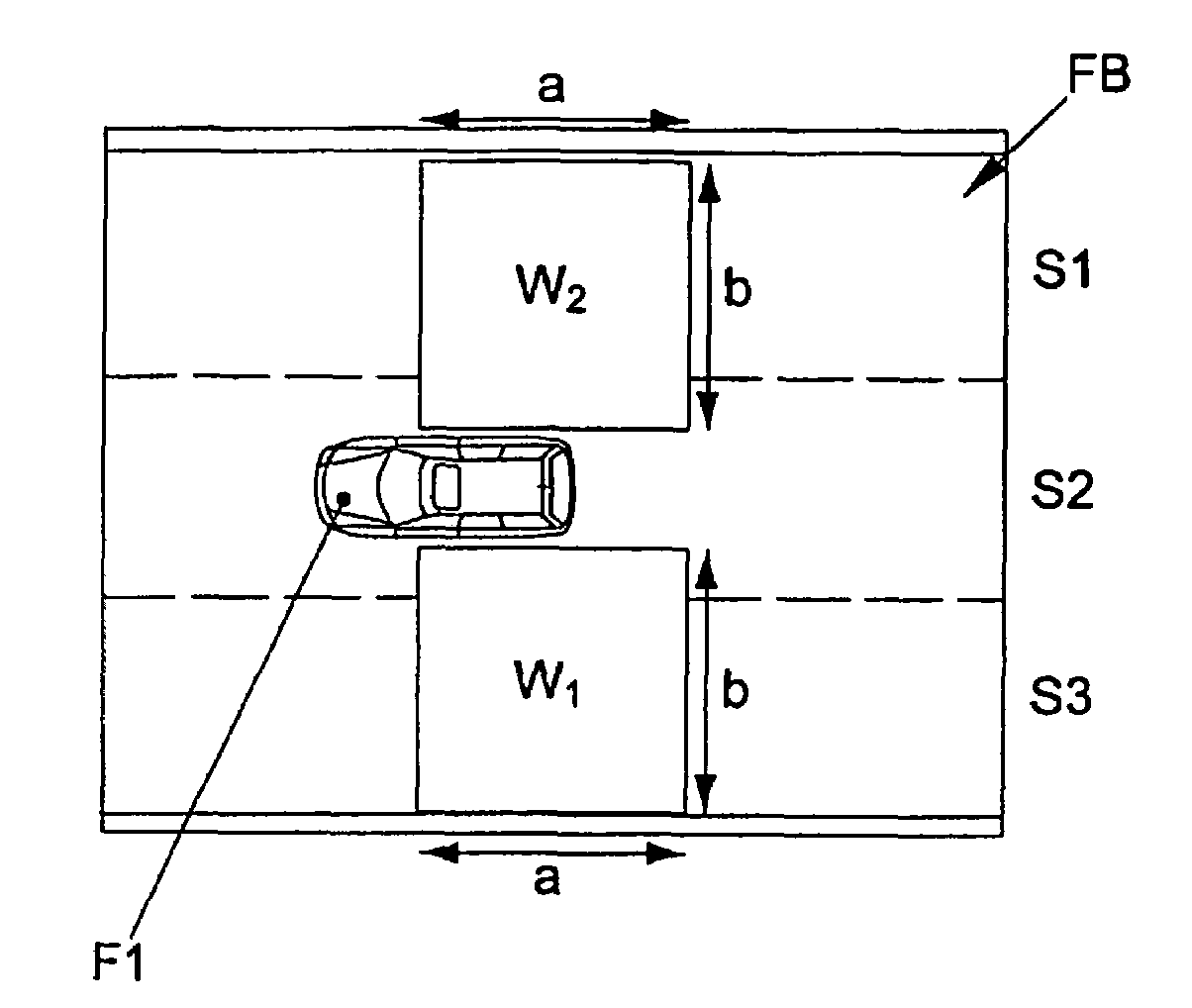
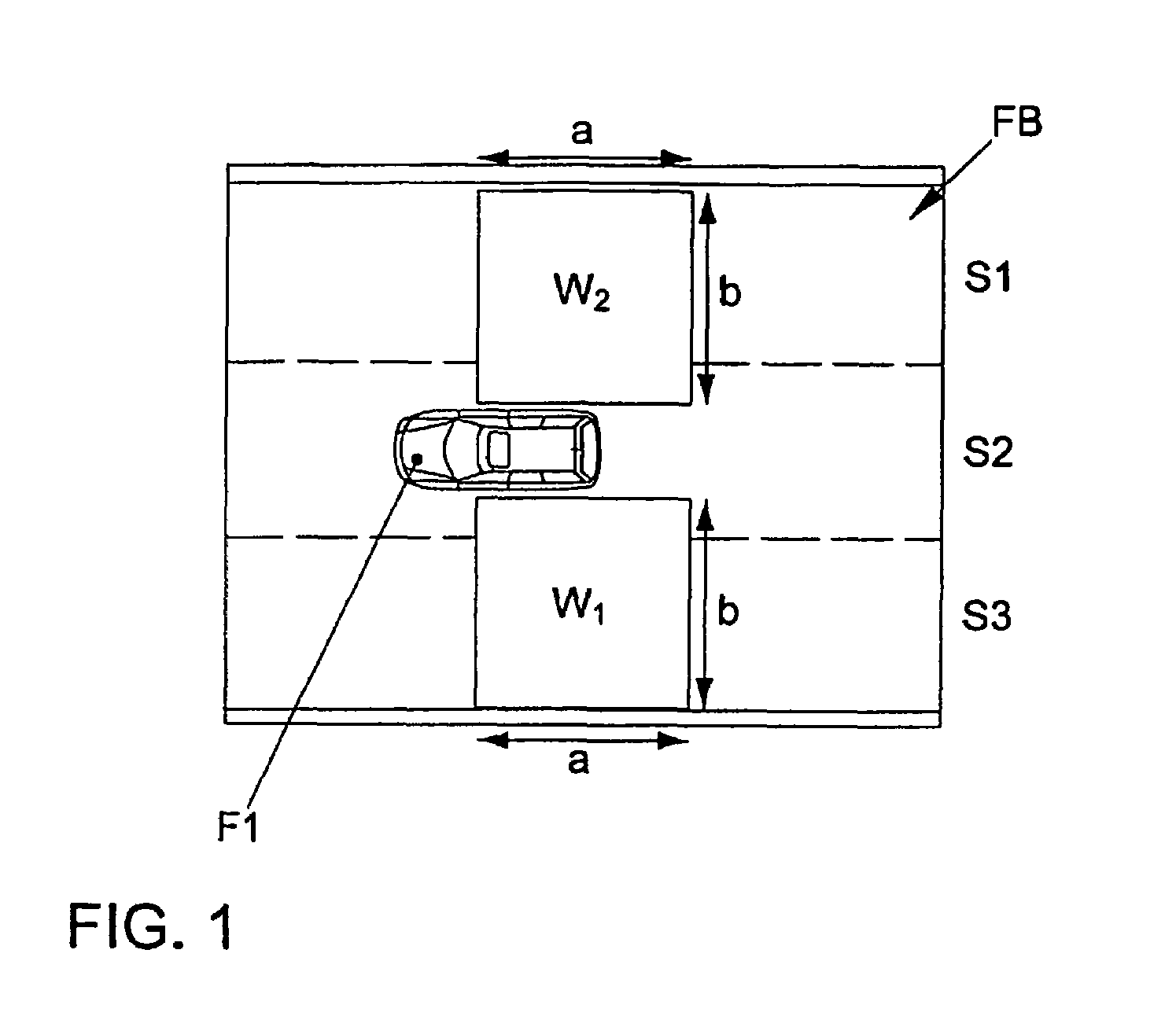
[0028]FIG. 1 is a schematic view of so-called blind spots on each side of a motor vehicle. What is shown is a motor vehicle F1 which is traveling from right to left in the drawing, in the middle lane S2 of a roadway FB having three lanes S1, S2, S3. Both on the driver's side and on the passenger's side, in each case a rectangular region W1, W2 is illustrated, having edges a, b which define, for example, a rectangle of approximately 5 m×5 m. These approximate regions W1, W2 are defined below as blind spot regions or warning regions, which are not able to be examined by the driver in the outside mirrors. The regions depend on the size and the sitting position of the driver, as well as on the type and the setting of the outside mirrors, as well as on the construction of the vehicle itself.

[0029]Furthermore, the size of the blind spot regions depends on the driving situation, such as the speed.

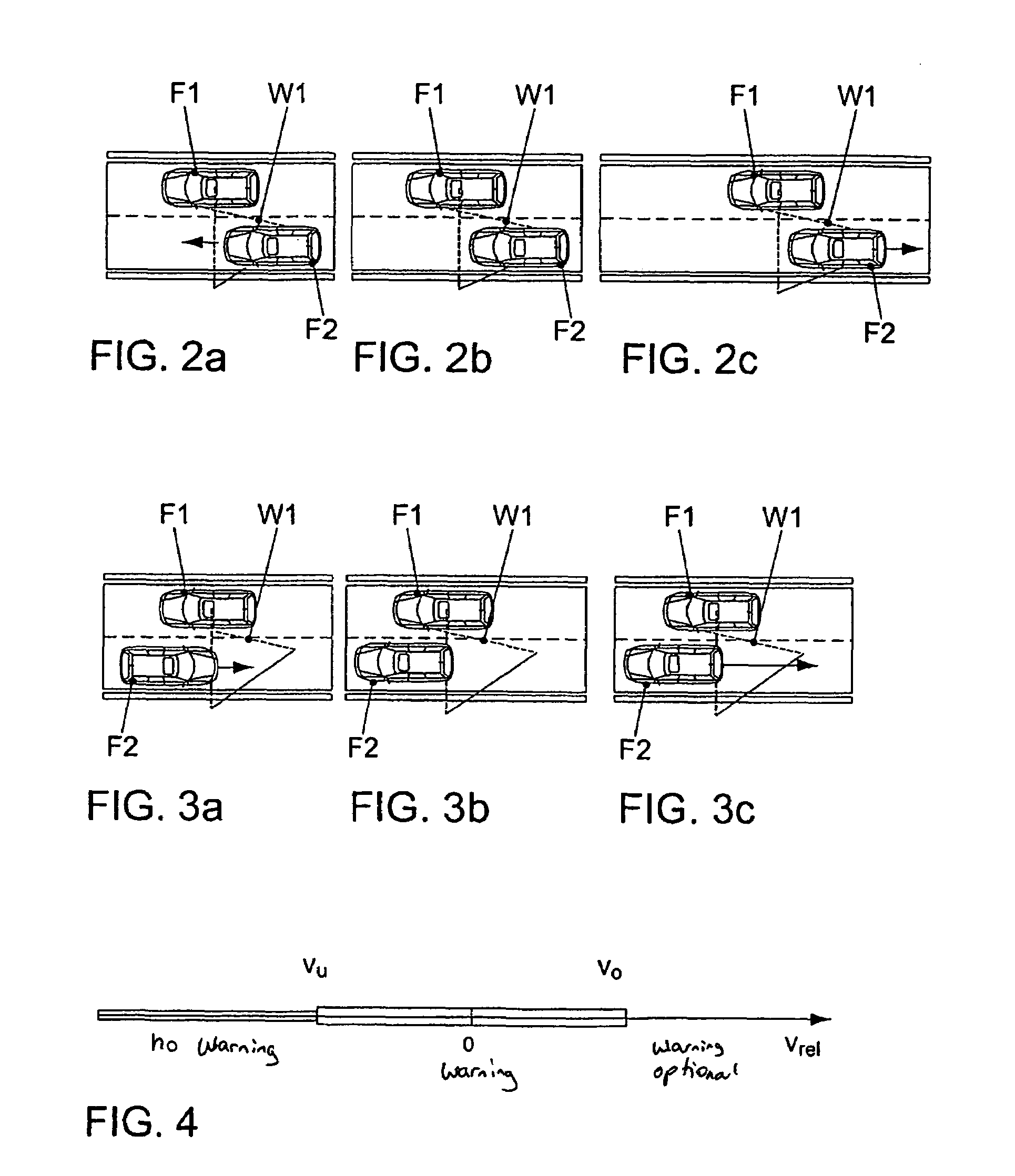
[0030]In the following FIGS. 2a to 2c, 3a to 3c, 5a to 5d, 6a to 6c, 7a to 7c and 8a to 8c, th...


PUM


Abstract

A method for monitoring the blind spot at the side of a motor vehicle, a warning function being activated which gives out a warning to the driver if an object is located in a warning region, includes the following steps: a) determining the relative speed between the object and the motor vehicle, determining the travel direction of the object relative to the motor vehicle, and determining the position of the object relative to the motor vehicle within a sensor region; and b) giving out a warning to the driver if the travel direction of the object corresponds to that of the motor vehicle, the relative speed between the object and the motor vehicle is within a predetermined range, defined by a lower range boundary and an upper range boundary, the predetermined region including the relative speed zero, and the position of the object being within the warning region.

Description

FIELD OF THE INVENTION[0001]The present invention relates to a method and a device for monitoring blind spots of a motor vehicle.BACKGROUND INFORMATION[0002]A driver of a vehicle is able directly to examine the region around his vehicle through the vehicle's windows, and indirectly through the vehicle's rear view mirrors. In this context, the driver is able to examine through the vehicle's windows predominantly the region in front of the vehicle and at the sides of the vehicle, whereas the region behind the vehicle may be examined using the vehicle's inside rearview mirror, and the regions laterally behind the vehicle may be examined using one or more of the vehicle's outer rearview mirrors.[0003]Because of the restricted field of view of the driver and the geometrical relationships in a vehicle, that is, for example, because of posts between the vehicle's windows that hinder vision, it is generally not possible for the driver of the vehicle to examine all the regions around a vehic...

Claims


Application Information

Patent Timeline
Patent Type & Authority Patents(United States)
IPC IPC(8): B60R21/00G01S13/931
CPCG01S13/931B60T2210/32G01S2013/9332G01S2013/9385G01S2013/9389G01S2013/9396G01S2013/93277G01S2013/93274G01S2013/9315G01S2013/93275
Inventor BARTELS, ARNE
Owner VOLKSWAGEN AG
Why Eureka
Try Eureka